Here's a link to his post about that.Dammitboy wrote:Detailed pics would be great, need to make one of these also.
zach-s-build-thread-t470446-400.html#p5842605
Here's a link to his post about that.Dammitboy wrote:Detailed pics would be great, need to make one of these also.

Do you know which fuse you used? I understand the logic behind a relay and I think I have a pretty strong grasp on how this all needs to be set up, BUT I'm the kind of person that needs to make sure; I prefer to make sure it's right the first time around.mtmetzger wrote:Just put another relay under the dash.
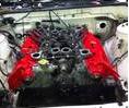
30 - Brown / Yellow in white connector (power to coils)
85 - Grey / Red wire in White connector (to pin 16 on ECU) (-) trigger from ECU
86 + 87 - Ignition power from key switch (or in my case switched power relay under dash)
This is exactly right except on my diagram the B/W never really says where it goes... Just says to fuse block, but it's the same B/W wire that powers the fuel pump relay on the Q. I don't see the need to run a constant power wire to the relay at all, that's why I jumpered my coil side of the relay to the feed side.. Both will be powered when ignition is on anyway and only when the ignition is on. Plus I ran some stout wire from my switched power circuit to it so no need to worry about them drawing too much current. (Like I said, I put mine under the dash) Since you are doing wiring in the fuse box, and I'm not sure how much current the ignition coils draw, I would go ahead and run a wire on out to the battery with a 30A fuse on it and connect that one to the relay at position 4. Of course you could hide the fuse in a blank slot in the fuse box.speedeast wrote:I'm assuming the power source (which is also the power source for ignition and fuel pump relays in the Q45; B/W wire) is a 30amp constant source (illegible in my diagram) and connects to the #5 pin. The destination of the current (coils; Br/Y wire) should be connected to the #3 pin. The #1 pin in the Q45 is a 30amp source when the ignition is ACC/ON/ST (W/B wire). The remaining #2 pin is connected to the ECU and the ECCS Relay (Gy/R wire).