Z32 project rescue (pic Heavy)
Re: Z32 project rescue (pic Heavy)
I actually had a really hard time finding anything for the S2. But from what ive read the only thing you would need to change is the o2 and knock wiring. Thats what I did, (spliced o2 wires together, to the one on the RB harness, and then the two knock wires on the RB harness to the one on the z32) runs fine, no CEL Yet.
-
JayNoel

- Posts: 119
- Joined: Sun Nov 22, 2009 4:41 pm
- Car: 90 RBZ32 rescue project
- Location: Bethlehem pa
Re: Z32 project rescue (pic Heavy)
Zkyline wrote:I actually had a really hard time finding anything for the S2. But from what ive read the only thing you would need to change is the o2 and knock wiring. Thats what I did, (spliced o2 wires together, to the one on the RB harness, and then the two knock wires on the RB harness to the one on the z32) runs fine, no CEL Yet.
Ok cause I Spliced the F2 (z32 dash harness plug) to the RB F3 (engine harness plug) and found all the matching wires. There was about 10 so far I hooked up out of the 13 on the F2 plug. Ill do a diagram of what I hooked up tonight. It would be nice for someone to double check what I did. Theres a big orange wire that says its for the air regulator/fuel pump relay but I already have one wire for a fuel pump relay and cant find anything on the rb harness F3 plug for that wire.
Re: Z32 project rescue (pic Heavy)
I have 3 conflicting diagrams. One lists that as orange, another as lt. Green. And yet another that says pin 104: ? Lol. Did you do the fuel temp resistor mod? I didnt bother doing it.
-
JayNoel
- Posts: 119
- Joined: Sun Nov 22, 2009 4:41 pm
- Car: 90 RBZ32 rescue project
- Location: Bethlehem pa
Re: Z32 project rescue (pic Heavy)
I saw it on the nistune mod instructions for when I get my type 2 board. In the ECU pin out for the RB to z32 ecu you take out pin 36 and put it into pin 33. I take it pin 33 is no longer needed? But in their instructions its only for series 2 rb25Zkyline wrote:I have 3 conflicting diagrams. One lists that as orange, another as lt. Green. And yet another that says pin 104: ? Lol. Did you do the fuel temp resistor mod? I didnt bother doing it.
heres the link for the PDF http://nistune.com/docs/Z32_ECU_Modific ... n%20V6.pdf
Re: Z32 project rescue (pic Heavy)
I tried several resistors (for different temps), didnt seem to make any difference. I imagine if you wanted it to read correctly, or at a "set" value for tuning reasons it may be important. I am going to run a APEXI SAFC piggyback fuel controller, once I put my Holset on, so I kinda started ignoring some of the Nistune steps. Lol
-
JayNoel
- Posts: 119
- Joined: Sun Nov 22, 2009 4:41 pm
- Car: 90 RBZ32 rescue project
- Location: Bethlehem pa
Re: Z32 project rescue (pic Heavy)
Zkyline wrote:I tried several resistors (for different temps), didnt seem to make any difference. I imagine if you wanted it to read correctly, or at a "set" value for tuning reasons it may be important. I am going to run a APEXI SAFC piggyback fuel controller, once I put my Holset on, so I kinda started ignoring some of the Nistune steps. Lol
This is my wiring so far before I loom it. Once it's running I'll do it in case I made an oops lol
Yellow - z32 f2 plug
Pink- fuel pump relay wire (pink/black)? Conflicts with bigger Orange wire
Orange- iavc F7 fuel pump relay?
Green- rbf3 plug
Red- Bee*R rev limiter connection
Blue- Greddy profec Eo-1 electronic boost controller
Blue X- old auto computer plug from auto to manual swap

-
JayNoel
- Posts: 119
- Joined: Sun Nov 22, 2009 4:41 pm
- Car: 90 RBZ32 rescue project
- Location: Bethlehem pa
Re: Z32 project rescue (pic Heavy)
Hopefully picking up a welder this weekend with a spool gun. Then I need Tig attachments so I can start the exhaust and FMIC piping (Spool gun for aluminum)
Re: Z32 project rescue (pic Heavy)
My wiring harness ended up more vg than RB. lol. One thing I ended up having to do, which is time consuming, but works, is using a power wire (or actual power probe if you have one) and then you can connect at the ecu plugs how you have them now, and check at the connectors in the compartment, and then you will be 100% sure of your wiring.
Also I have a GTR pan, and had to spoolgun the axle holes shut, lol, I know the struggle.
Also I have a GTR pan, and had to spoolgun the axle holes shut, lol, I know the struggle.
-
JayNoel
- Posts: 119
- Joined: Sun Nov 22, 2009 4:41 pm
- Car: 90 RBZ32 rescue project
- Location: Bethlehem pa
Re: Z32 project rescue (pic Heavy)
So i was doing some digging online and CX racing offers a whole FMIC and rad setup Im thinking about getting
http://www.cxracing.com/mm5/merchant.mv ... Code=300ZX

$698 plus $50 for shipping and its completely bolt in no cutting of the rad support so I would have to weld mine back in
http://www.cxracing.com/mm5/merchant.mv ... Code=300ZX
$698 plus $50 for shipping and its completely bolt in
-
NolimitZ32

- Posts: 7042
- Joined: Fri Jun 27, 2008 9:07 am
- Car: 91 AG2 2+0 TTMT swap/E39 BMW 540i6/E53 4.6is Dinan S3
- Location: Houston, TX
Re: Z32 project rescue (pic Heavy)
CX Racing doesn't have the best reputation for good fitment but other than that it looks like a pretty awesome deal. To make the system work efficiently you need to make sure there is a draw out for the Intercooler and the radiator which the car is not designed for, its something you'll have to do yourself, not too difficult if you are handy though, just something to think about.
-
JayNoel
- Posts: 119
- Joined: Sun Nov 22, 2009 4:41 pm
- Car: 90 RBZ32 rescue project
- Location: Bethlehem pa
Re: Z32 project rescue (pic Heavy)
NolimitZ32 wrote:CX Racing doesn't have the best reputation for good fitment but other than that it looks like a pretty awesome deal. To make the system work efficiently you need to make sure there is a draw out for the Intercooler and the radiator which the car is not designed for, its something you'll have to do yourself, not too difficult if you are handy though, just something to think about.
So to make it work this is what Ive found online.

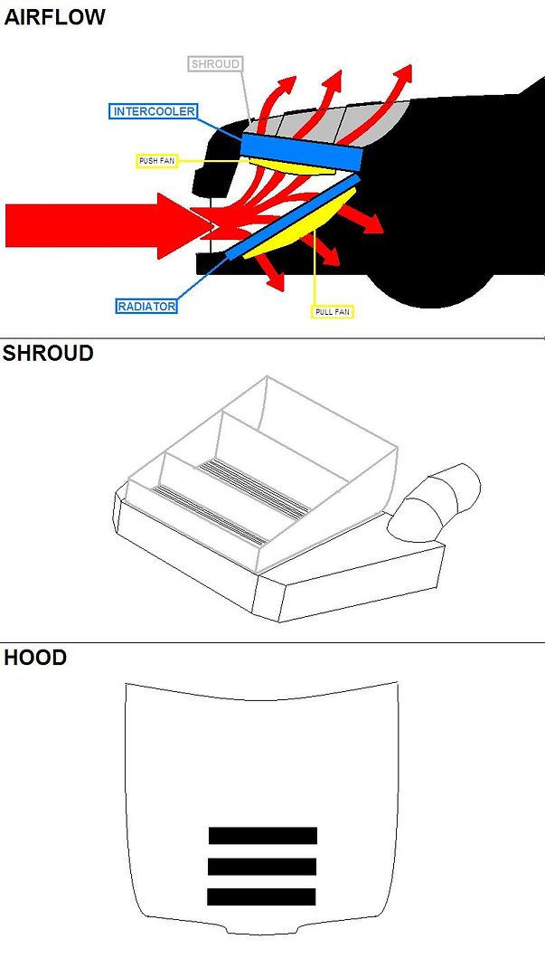

Push or pull fan for the rad?
but instead of the vent being in the hood for the inter cooler have the vent on the panel between the headlights?
I cant find a vent panel I like tho
-
JayNoel
- Posts: 119
- Joined: Sun Nov 22, 2009 4:41 pm
- Car: 90 RBZ32 rescue project
- Location: Bethlehem pa
Re: Z32 project rescue (pic Heavy)
I think this bumper will allow the most airflow too

-
NolimitZ32
- Posts: 7042
- Joined: Fri Jun 27, 2008 9:07 am
- Car: 91 AG2 2+0 TTMT swap/E39 BMW 540i6/E53 4.6is Dinan S3
- Location: Houston, TX
Re: Z32 project rescue (pic Heavy)
The issue with having the vent in the nose panel may be that during high speed you'll be counteracting the flow. I can't say whether this is actually true or not since I've never seen this car in a wind tunnel especially with an aftermarket nose panel but its something to think about.
-
JayNoel
- Posts: 119
- Joined: Sun Nov 22, 2009 4:41 pm
- Car: 90 RBZ32 rescue project
- Location: Bethlehem pa
Re: Z32 project rescue (pic Heavy)
NolimitZ32 wrote:The issue with having the vent in the nose panel may be that during high speed you'll be counteracting the flow. I can't say whether this is actually true or not since I've never seen this car in a wind tunnel especially with an aftermarket nose panel but its something to think about.
If you look at the picture that CX racing has there is a lot of room for the air to flow over the "top" part of the intercooler back toward the engine. It looks like it's about 3-4 inches below the hood latch and level with the front bumper support. I would hope any air coming in a vented nose panel would create a "pull" effect with the air coming up through the VMIC. That's my theory tho. I guess I'll find out haha
-
JayNoel
- Posts: 119
- Joined: Sun Nov 22, 2009 4:41 pm
- Car: 90 RBZ32 rescue project
- Location: Bethlehem pa
Re: Z32 project rescue (pic Heavy)
Wind tunnel video
-
JayNoel
- Posts: 119
- Joined: Sun Nov 22, 2009 4:41 pm
- Car: 90 RBZ32 rescue project
- Location: Bethlehem pa
Re: Z32 project rescue (pic Heavy)
Well I found a video but its not loading here is the link
https://www.youtube.com/watch?v=OuVf7cLCqiQ
https://www.youtube.com/watch?v=OuVf7cLCqiQ
Last edited by JayNoel on Fri Dec 18, 2015 1:27 pm, edited 1 time in total.
-
JayNoel
- Posts: 119
- Joined: Sun Nov 22, 2009 4:41 pm
- Car: 90 RBZ32 rescue project
- Location: Bethlehem pa
Re: Z32 project rescue (pic Heavy)
you can see how much space there is in this picture for airflow

-
NolimitZ32
- Posts: 7042
- Joined: Fri Jun 27, 2008 9:07 am
- Car: 91 AG2 2+0 TTMT swap/E39 BMW 540i6/E53 4.6is Dinan S3
- Location: Houston, TX
Re: Z32 project rescue (pic Heavy)
That wind tunnel video does absolutely nothing, you need to be able to see how the airflow behaves at the nose panel with the v-mount setup in place and different types of nose panels. As for open flow into the engine bay, you aren't creating a pulling effect, you are causing a blockage because once the air enters through the v-mount it stagnates in the engine bay as there is nowhere for it to go. And all areas where the air could potentially exit from the engine bay are surrounded by fast moving airflow creating a high pressure and encapsulating the air within the engine bay. This is why all the properly built v-mount setups you see have a pretty outrageously shaped openings in the hood and ducting. What has to be done is an area of low pressure has to be created where you want the hot air from the inter-cooler to go, this will effectively pull the airflow through the inter-cooler increasing efficiency. Read through this to get a little better understanding http://ateupwithmotor.com/terms-technol ... od-scoops/ Now keep in mind, not doing any of this and just sticking the setup in as is wont have detrimental effects especially if you install fans., what I am talking about is achieving maximum efficiency of the system.
-
JayNoel
- Posts: 119
- Joined: Sun Nov 22, 2009 4:41 pm
- Car: 90 RBZ32 rescue project
- Location: Bethlehem pa
Re: Z32 project rescue (pic Heavy)
NolimitZ32 wrote:That wind tunnel video does absolutely nothing, you need to be able to see how the airflow behaves at the nose panel with the v-mount setup in place and different types of nose panels. As for open flow into the engine bay, you aren't creating a pulling effect, you are causing a blockage because once the air enters through the v-mount it stagnates in the engine bay as there is nowhere for it to go. And all areas where the air could potentially exit from the engine bay are surrounded by fast moving airflow creating a high pressure and encapsulating the air within the engine bay. This is why all the properly built v-mount setups you see have a pretty outrageously shaped openings in the hood and ducting. What has to be done is an area of low pressure has to be created where you want the hot air from the inter-cooler to go, this will effectivelypull the airflow through the inter-cooler increasing efficiency. Read through this to get a little better understanding http://ateupwithmotor.com/terms-technol ... od-scoops/ Now keep in mind, not doing any of this and just sticking the setup in as is wont have detrimental effects especially if you install fans., what I am talking about is achieving maximum efficiency of the system.
I found some more info on a Rx7 group http://www.rx7club.com/single-turbo-rx- ... ic-820753/
They agree with what your saying too. Adding some more holes to my hood might work with the polished/rust look. I was thinking about putting some type of mesh or grill under the image on the hood. If I can get away with not venting the nose panel I'd like to do that. I like the one I have lol benefit would be the image is right where my turbo sits. Need some shielding for the master cyl too. The turbo sits pretty close
Re: Z32 project rescue (pic Heavy)
Get a turbo blanket too. Should only be like $25
Re: Z32 project rescue (pic Heavy)
You should see how I just did mine, the screamer pipe was melting my wiring, so I wrapped it all in reflective fiberglass insulation, and the pipe in header wrap. Also did the brake master cyl. Like you said. Hey, btw if you need anymore wiring help, PM me again, but ENABLE PMs! I couldnt respond lol
-
JayNoel
- Posts: 119
- Joined: Sun Nov 22, 2009 4:41 pm
- Car: 90 RBZ32 rescue project
- Location: Bethlehem pa
Re: Z32 project rescue (pic Heavy)

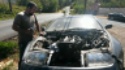
She's getting closer
-
DCaff300ZX

- Posts: 4202
- Joined: Sun Jun 14, 2009 8:18 am
- Car: .
1993 CRP TT- Modified - Location: Tacoma, Washington
Re: Z32 project rescue (pic Heavy)
Haven't seen this in awhile, WOW.
This is getting pretty wild, and I like it...
This is getting pretty wild, and I like it...
-
Monkton
- Posts: 14
- Joined: Tue Jan 12, 2016 7:07 pm
- Car: 1990 300zx
S2 RB25det swap - Location: Monkton MD
Re: Z32 project rescue (pic Heavy)
Great build! I'm currently doing a S2 RB w/ the r33 5sp trans on a 1990 2 seater n/a 5sp car. I'm using a few of the cx racing parts and have been very satisfied at the quality for the price point. Lots of good info in this thread.
-
raremotive

- Posts: 3581
- Joined: Sun Oct 07, 2007 8:54 pm
- Car: 04 Infiniti G35
- Location: Stuck in the middle.
Re: Z32 project rescue (pic Heavy)
Very nice progress.
Any plans to put in a air bleeding system for your RB? It's a pretty common mod to help burp air out the engine while it runs. Usually helps keeping the motor cooler if you don't have air pockets hanging out inside the head of the engine.


V-mount systems are pretty cool in a sense. The trick is to direct the air more inline to the windshield of the car. This helps with the streamlining. If you don't this could potentially increase your CD essentially making your front end a plow.

Any plans to put in a air bleeding system for your RB? It's a pretty common mod to help burp air out the engine while it runs. Usually helps keeping the motor cooler if you don't have air pockets hanging out inside the head of the engine.
V-mount systems are pretty cool in a sense. The trick is to direct the air more inline to the windshield of the car. This helps with the streamlining. If you don't this could potentially increase your CD essentially making your front end a plow.