I was trying to replace the bushings on the rack this evening and managed to get the passenger bushing on but no chance with the driver side. It looks like I am going to have to remove the rack to get the new bushing on the left side. As far as removing goes, does anybody have any suggestions on how to go about removing, reinstalling, and bleeding the rack after I get the new bushings on?Thanks,MattJacksonville, FL
P.S. I am almost thinking about getting a rebuilt one from autozone except for the fact that I have already purchased new boots for the rack I have now.
Replacing rack bushings on 91 Q45
Re: Replacing rack bushings on 91 Q45 (mattd1979)
I recently ordered two bushings from Joe (they haven't arrived yet).mattd1979 wrote:any suggestions on how to remove the rack to get the new bushings on?
In the 1990 Q45 oilpan R&R related thread (http://www.nicoclub.com/zerothread?id=77266), I just asked a similar question (before I saw this new thread from you).
I'd love to know the answer to these questions: a) How to remove the rack (is it the four bolts shown in the photo below)? b) Where do those two bushings actually go (what is the R&R procedure)? c) How do you know if the originals need replacement in the first place?
In addition, I should caution you (as I was cautioned in the oil pan R&R thread) to remove: a) The electrical connector to the steering rack (somewhere in the middle) b) The steering lower joint (underneath the driver's feet) upper bolt c) The steering lower joint lower bolt (and disconnect from the rack)
DISCLAIMER: I haven't done anything of the above (yet) other than the steering lower joint lower bolt ... so take any help I give with a grain of salt and take anyone elses recommendations over mine.
-
Q451990

- Moderator
- Posts: 11030
- Joined: Tue Jul 23, 2002 8:21 am
- Car: 1990 Q45 - 118K, 2022 Toyota 4 Runner, 2004 Frontier M/T - 108K, 2012 Xterra (Mom's), 2023 Rogue (Inlaws)
- Location: Columbia, SC
- Contact:
Re: Replacing rack bushings on 91 Q45 (mattd1979)
Be sure to loosen and remove the u-joint that connects the steering column to the rack. I think I did it without that step on "Q1" and it took an hour or so of painful work. I removed that u-joint when I replaced them on "Q2" and it went on pretty easily. You definately do not have to remove the rack to replace the bushings.
Here's a pic of the joint that I borrowed from Tangalora's oil pan thread...
http://www.nicoclub.com/zerofi...t.jpg
Heath
Here's a pic of the joint that I borrowed from Tangalora's oil pan thread...
http://www.nicoclub.com/zerofi...t.jpg
Heath
-
elwesso
- Posts: 30810
- Joined: Sun Feb 23, 2003 4:52 pm
- Car: 94 Infiniti Q45t 5 spd
2007 BMW M Coupe
2007 Infiniti G35 S 6MT - Location: Indiana
- Contact:
Re: Replacing rack bushings on 91 Q45 (tangalora)
Tangalora, the things you listed ONLY apply to you because you are dropping the egnine cross member... The 2 brackets just come off when your only replacing the bushings... You dont take out the rack...tangalora wrote:I recently ordered two bushings from Joe (they haven't arrived yet).
In the 1990 Q45 oilpan R&R related thread (http://www.nicoclub.com/zerothread?id=77266), I just asked a similar question (before I saw this new thread from you).
I'd love to know the answer to these questions: a) How to remove the rack (is it the four bolts shown in the photo below)? b) Where do those two bushings actually go (what is the R&R procedure)? c) How do you know if the originals need replacement in the first place?
In addition, I should caution you (as I was cautioned in the oil pan R&R thread) to remove: a) The electrical connector to the steering rack (somewhere in the middle) b) The steering lower joint (underneath the driver's feet) upper bolt c) The steering lower joint lower bolt (and disconnect from the rack)
DISCLAIMER: I haven't done anything of the above (yet) other than the steering lower joint lower bolt ... so take any help I give with a grain of salt and take anyone elses recommendations over mine.
Did you look at the picture that I posted in the other thread.. I will post it again... THe red circled things are the rack bushings, and they go down on the rack where the arrows point..... Let me try and answer each question individually
1.a. Thats correct, that unbolts the rack from the member, but you cannot remove it just that easy.. there are semi circle things holding it in, i think.. Bottom line is crossmember comes down for rack to come outb. Just remove both bolts, and slide the joint up the steering shaft (so its disconnected from the rack). its important to lock the steering wheel in place and make marks on the rack so that you can align it back up againc. See B
2. (a,b,c). The conncetor doesnt hvae to be removed...
-
elwesso
- Posts: 30810
- Joined: Sun Feb 23, 2003 4:52 pm
- Car: 94 Infiniti Q45t 5 spd
2007 BMW M Coupe
2007 Infiniti G35 S 6MT - Location: Indiana
- Contact:
Re: Replacing rack bushings on 91 Q45 (elwesso)
Also what the diagram does not show is that they are not whole.. meaning they are cut in one section so you wrap it around the steering rack... you dont slide it on from the side or anything (i could only imagine!)
Re: Replacing rack bushings on 91 Q45 (elwesso)
Wes is correct, as usual. Here's a shot of two new 1990 Q45 steering rack bushings from Joe labelled:- INSULATOR LH (presumably this is for the driver's side) P/N: 54445-60U00 - INSULATOR (presumably this is for the passenger side): P/N: 54444-61U00elwesso wrote:... the diagram does not show [the bushings] are not whole.. meaning they are cut in one section so you wrap [them] around the steering rack ...
Re: Replacing rack bushings on 91 Q45 (Q451990)
Listen to Heath; he speaks words of wisdom.Q451990 wrote:Be sure to loosen and remove the u-joint that connects the steering column to the rack. I think I did it without that step on "Q1" and it took an hour or so of painful work ...
I too (incorrectly, it turns out miscalculated by only removing the LOWER bolt of the "steering lower u joint". I had hoped that the heavy engine crossmember & steering rack assembly would just pull the u-joint off the steering rack. Well, I was wrong. The crossmember would not drop on the driver's side due to this faux pas of mine. Those who follow suit should listen well.
Remove (at least) the UPPER bolt of the "steering lower u joint"!
When I belatedly removed this upper bolt and then lowered the heavy front engine crossmember via a floor jack centered on the crossmember, the "steering column lower u joint" easily popped off the splined "steering column lower shaft" (given the weight of the crossmember & steering rack assembly bolted to the crossmember).
Note: Folks on another thread (oilpan R&R) recommended marking the steering column lower shaft & steering column lower U-joint. I hope I marked this correctly. Also note the flat spot in the steering column lower shaft coincides with the location of the upper set screw bolt that needs to be removed as shown in the photo below.
Why do we mark the steering column splines?
Oh (sheepish look on my face), I (think I) finally get it.Q451990 wrote:As long as you don't rotate the steering wheel, the marks are not a big deal.
If I were to rotate the steering wheel, say, 360 degrees, then the flat spot on the steering column lower shaft spline would be in the same place it is now (see photo below) ... and the splined shaft would still fit perfectly into the steering column lower u joint ... but the steering wheel would be "offset" by a complete turn???
Thanks for that hint. I hadn't thought of that. This hint will help others (in the future) too.
But, I'm still confused on one issue:Why do we bother to mark the steering column lower shaft and u joint?
The white markings in the photo below appear meaningless (at least to me given my meager understanding so far). There's no way I can put that spline on any other way than aligning the flat spot with the set bolt.
What I (think I) really should have done is lock the steering wheel before I disconnected the lower steering u-joint from the splined lower steering column.
Maybe I could tie the steering wheel to the brake pedal with rope or wire? Naah. I just won't move the steering wheel (as you suggested).
Do I (now) understand the problem correctly? - Marking the splined shaft & u joint does us no good; - What we need to do is [u[not spin the steering wheel (relative to its current position with the spline)

Re: (DAEDALUS)
I think Daedalus might be right. You problably could reasemble the shafts off by a spline or two but I wonder if it would make any difference if the splines were off by a few. Would it?DAEDALUS wrote:if you were off 1 spline you could still tighten the screw down on it.
Also it must be tough to mark that splined shaft acurately being that it must be greasy and dificult to get to. What did you use that showed up so wavy yet brite? Paint? Chalk? Crayon? In the jpeg I cant tell if you can tell a spline or two off but I suspec that you cant tell anyway so thats why I wonder if it makes a difference if you are off a spline or two?
Steering insulator marking of LH must indicate passenger side (wierd)
Indeed. I stand corrected. The round steering rack "insulator" appears to be on the passenger side (not the driver side).911/Q45 wrote:the round bushing goes on the passenger side and the funny shaped one on the driver's side.
What threw me off was the "LH" printed marking on the Nissan Motor Corporation package label for the round-shaped "insulator" (aka steering rack bushing). I assumed that meant "left hand" from the perspective of the driver. LH would have been the driver side. If LH does mean left hand, it must be from a head-on perspective instead.
I can (now) see both from the diagram (which is from a head-on perspective) and from the attached photo below (which was snapped from the driver's perspective) that the wierd-shaped steering rack "insulator" is indeed on the driver side.
Thanks for clearing that up. I think I'll concentrate on the oil pan R&R first, and then try to remove these bushings, although I regret I didn't loosen the four steering rack crossmember bolts first.
Q: Do you think I first should have loosened the four large bushing bolts while the front engine crossmember was still firmly attached to the Q45 body?
Re: (mixatonia)
Whiteout.mixatonia wrote:What did you use that showed up so wavy yet brite? Paint? Chalk? Crayon?
Basically I used white paint in a small jar with a teeny tiny applicator brush that must've made someone a millionaire given the price we pay for a tiny jar of paint (I'd have used automotive touch-up paint but that's even more expensive than plain old whiteout).
-
Q451990
- Moderator
- Posts: 11030
- Joined: Tue Jul 23, 2002 8:21 am
- Car: 1990 Q45 - 118K, 2022 Toyota 4 Runner, 2004 Frontier M/T - 108K, 2012 Xterra (Mom's), 2023 Rogue (Inlaws)
- Location: Columbia, SC
- Contact:
Re: (DAEDALUS)
I think the u-joint and the shaft are both keyed. I just remember fiddling around with this and noting that it was not possible to put it back wrong. In any case - it's never a bad idea to mark parts before removing them! What you don't want to do is spin the steering wheel several times and damage the spiral cable. I think Tangalora's idea of locking the wheel is a good one.DAEDALUS wrote:I think marking the steering column is important. The steering wheel is not the only thing that can move. Looking at the picture, the flat spot has no effect on the orientation of the splines, and if you were off 1 spline you could still tighten the screw down on it.
BTW - my u-joint was frozen on Q1. I noticed that the steering felt very tight and notchy at first, and then felt better after driving for a while. I think the heat from the nearby pre-cat loosened everything up just enough to get it moving. I've never heard of another failure - but while you have the u-joint off, check it for excessive notchy-ness or stiffness.
Heath
What spiral cable?
Spiral cable?Q451990 wrote:What you don't want to do is spin the steering wheel several times and damage the spiral cable.
(I just leafed through the ST steering section of the 90 FSM and I don't see mention or diagram of a spiral cable anywhere)
I'm curious (as usual) ... Where is this spiral cable?And, more importantly:What do I not do so as to not damage it?
-
elwesso
- Posts: 30810
- Joined: Sun Feb 23, 2003 4:52 pm
- Car: 94 Infiniti Q45t 5 spd
2007 BMW M Coupe
2007 Infiniti G35 S 6MT - Location: Indiana
- Contact:
Re: (911/Q45)
I didnt read all the replies, but in regards to the steering wheel.. Make sure the wheels are pointed correctly, and then take the key out and lock the wheel straight foreward, or whatever it will be... then youll have no choice but to put it on right...
Thats how I messed up with jesda's Q, we didnt lock or mark...
Thats how I messed up with jesda's Q, we didnt lock or mark...
Re: (911/Q45)
Oh. Wow. Didn't know that. Didn't even know I didn' t know that.911/Q45 wrote:if you spin the wheel freely while it's disconnected from the rack, you'll break the spiral connection cable behind the airbag in the steering wheel
The 90 FSM merely says "Remove steering lower joint" next to a diagram with everything shown except the steering lower joint (page EM-11, diagram SEM866C). You'd think it would show the steering lower joint that needed to be removed (not the result afterward).
I'll add your spiral-cable admonishment to my handwritten notes (hopefully to be a useful article).
P.S. I guess I'm getting some experience because that EM-11 diagram purporting to show how to remove the steering lower joint is actually a diagram of everything but the steering lower joint! It looks familiar to me, now ... but only because I removed the steering lower joint and I now realize what those two projections in the diagram really are!
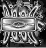
Passenger side steering rack bushing (mounted)
Here, for the record, is a photo showing what you can not see from the underside of the Q.
It's a shot taken from above the steering rack showing the passenger side steering rack bushing (aka rubber insulator) and its two mounting attachment bolts and the u-shaped plate holding it all together.
It's a shot taken from above the steering rack showing the passenger side steering rack bushing (aka rubber insulator) and its two mounting attachment bolts and the u-shaped plate holding it all together.
Re: Passenger side steering rack bushing (tangalora)
Here is a shot of the removal of the 22mm rearward bolt (which can be accessed with a "normal" socket).
Note: I used a 22 mm impact socket because I had to resort to a 30 inch long by 1 inch inside diameter pipe over my breaker bar to get the bolt out of the front engine crossmember.
Note: I used a 22 mm impact socket because I had to resort to a 30 inch long by 1 inch inside diameter pipe over my breaker bar to get the bolt out of the front engine crossmember.
Forward (sunken) bolts for steering rack attachment
Here is a shot of the removal of the deeply set 22mm forward bolt (which can be accessed only with a six-inch socket extension).
Note again that it was impossible to crack those bolts without the leverage of the 30 inch pipe on the breaker bar (at least for me).
Note again that it was impossible to crack those bolts without the leverage of the 30 inch pipe on the breaker bar (at least for me).
Disassemble steering rack insulator from the rack
Once those two 22 mm bolts are removed on each side of the steering rack, here's a shot of the results.
Notice you can easily pry the u-shaped bracket plate upward so that you can more easily peel the rubber tight-knit c-shaped steering rack insulator out.
Notice you can easily pry the u-shaped bracket plate upward so that you can more easily peel the rubber tight-knit c-shaped steering rack insulator out.
Shot of the steering rack bushing bracket plate
Here, for the next poor soul, is a shot of the steering rack bushing bracket plate still on the front engine crossmember (but with the crossmember out of the car).
Notice how easily the thin steel plate can be bent upward to access the steering rack insulator bushings.
Notice how easily the thin steel plate can be bent upward to access the steering rack insulator bushings.
Re: Shot of the steering rack bushing bracket plate (tangalora)
The previous shot was of the passenger side steering rack bushing bracket plate on the crossmember.
Here's a shot of the driver-side steering rack bushing bracket plate off the crossmember.
Notice both steering rack bushing bracket plates have a few 10 mm bolts which hold the cover plate onto the front engine crossmember even with the four main 22 mm bolts removed.
Here's a shot of the driver-side steering rack bushing bracket plate off the crossmember.
Notice both steering rack bushing bracket plates have a few 10 mm bolts which hold the cover plate onto the front engine crossmember even with the four main 22 mm bolts removed.
What do you mean by "keyed"?
Heath,I'm not sure what you mean by "keyed".Q451990 wrote:I think the u-joint and the shaft are both keyed.
In the U-joint, there is one flute larger (and flatter) than the rest.
Is this the "keying" you bespoke of?
Re: What do you mean by "keyed"? (tangalora)
Correspondingly, upon closer inspection, the lower steering shaft seems to have a similar flat spot.
Is this what you mean by keying?
Is this what you mean by keying?
Re: What do you mean by "keyed"? (tangalora)
I could be wrong, but, a closer inspection of the thousands of photos I took of the job as it progressed doesn't seem to show that same corresponding keying of the lower half of the steering lower u-joint ... nor does it seem to show any keying of the nub of a splined shaft sticking out of the steering rack itself.
What the photos do show is some sort of small indentation (like for a set screw).
Any idea what that indentation is for?
What the photos do show is some sort of small indentation (like for a set screw).
Any idea what that indentation is for?
Re: What do you mean by "keyed"? (tangalora)
By way of backup evidence, notice this shot of the lower steering u-joint lower half does not seem (to me anyway) to show any evidence of the keying seen in the upper half.
Given the lack of obvious keying, and given the set-screw indentation, did I miss something?Is there a mechanical method inherent for auto-aligning of the lower half?
Given the lack of obvious keying, and given the set-screw indentation, did I miss something?Is there a mechanical method inherent for auto-aligning of the lower half?
-
skywise6854
- Posts: 72
- Joined: Wed May 04, 2005 4:18 am
- Car: 92 q45a
Re: What do you mean by "keyed"? (tangalora)
i would also like to point out that there was a question at the top of the thread that didnt get answered. question was how do you know you have to relace the insulators or bushings i cant say what anyone else experienced but my driver side bushing completely seperated from itself and the rack was sliding sideways inside the mounting brackets and it was making my steering all screwy especially if there were grooves in the road or going around any turn. as a side note the dealership spent 2 hours in diagnosing the prob and ended up telling me it was a fault in the active suspension and the ride hight was changing from side to side while driving therby giving the impression of not steering correctly then they attempted to hand me a 7500 dollar estimate for repairing or replacing active components. days later i decided to attempt to remove the rack for further inspection and found the problem myself it was kind of difficult to get the old melted hardened bushings cleaned off the metal rack and also to get the new insulator in i ended up using a little vaseline to slide it right around the rack cause i couldent force it in the groove otherwise and it was about 10 degrees outside and im lying on my back for hours getting hypothermia. hope i didnt ruin anything and i hope this helps anyone in the future.