Issue: (Crank sensor) etc.. listed
1- Don't know what the (3) WIRES are for. I assume 1 is ground ecu, and one is signal-then 3rd is shield... (
Without this, I can't proceed with tuning. I have rigged a breadboard using a 555 timer circuit to 'fake' a signal to test [newly built ecu] but ... would like to utilize a factory sensor (I think its a VR type) to do the tuning and get the computer correct before I map out the ecu.
2- How many teeth including missing are on the crank angle sensor trigger wheel located at/on the flywheel? (Pulling the transmission isn't an option now)
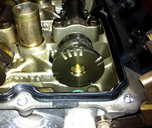
3- Why the heck does their can sensor have such a funky 1 / 3 / 4 / 2 trigger wheel?
4- Are the factory injectors High-z , or Low-z? meaning high impedence (5ohm+) or (2.5ohm+/-)
5- Are the COPs (Coil on plug) logic controlled from ecu (5v), or high current i.e. 12v? I believe the outside wires are 12v and center of 3 wire coil is trigger voltage signal.
Info:
2008 Titan motor
Rally car install
Megasquirt 3X with sequintial port injection and no wasted spark.
I can post progress for those interested as well.
Thnx in advance