Before we get too far into this, I've got a bit of a disclaimer. The following modifications are intended for off-road use only. Modifying or deleting these systems is illegal for vehicles that are used for transportation on public roadways. In states that perform emissions testing, you will very likely fail by performing any one of the modifications that are discussed. In some cases, the removal of certain emissions equipment is a federal crime. You alone are liable for any and all penalties or damages resulting from performing these modifications. NICOclub.com, myself, and the administrators of this forum and website cannot be held liable for your actions.
With that being said, please share your insights and experiences. What have you done to address EGR, PCV, carbon canister, catalytic converters, etc? How did you execute it? Have there been any negative effects - CEL, idle issues, smoking, etc? What have been the benefits - less clutter, cleaner intake manifold, ease of maintenance, better mileage?
I've got a 93 Q45 that I'm working on and it is basically stock. The previous owner told me it had bad injectors or something and I took his word. I pulled the upper intake and found that the resonator tube that ties in with the IAC y-pipe was disconnected. Then I saw that the knock sensors were cracked, so I dove in to a complete intake manifold tear-down.
As anyone that's ever had the intake manifold off a VH can attest, it's a mess under there - mostly due to a complicated PCV system. If you've gotten this far, you might as well make it easier on yourself for reassembly and whoever the poor soul is that has to get in there next time. So let's begin.
I want to start with a couple excerpts from the Factory Service Manual. If you haven't downloaded the one for your car or engine, you should. They're an indispensable resource and are available here for download. If you prefer a hard copy, they can be found on eBay sometimes. I've sampled the 93 manual as that's the year of car I have and what version of the hard copy I have. Most of this information should be the same for all years of the VH45.
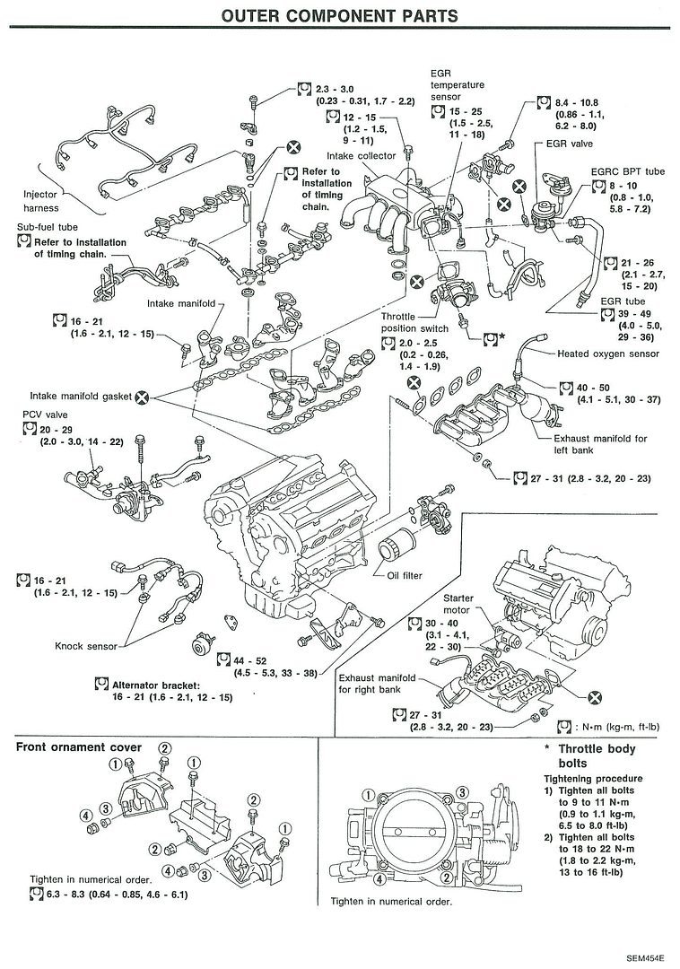
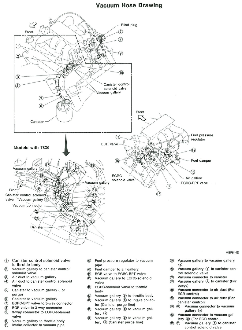
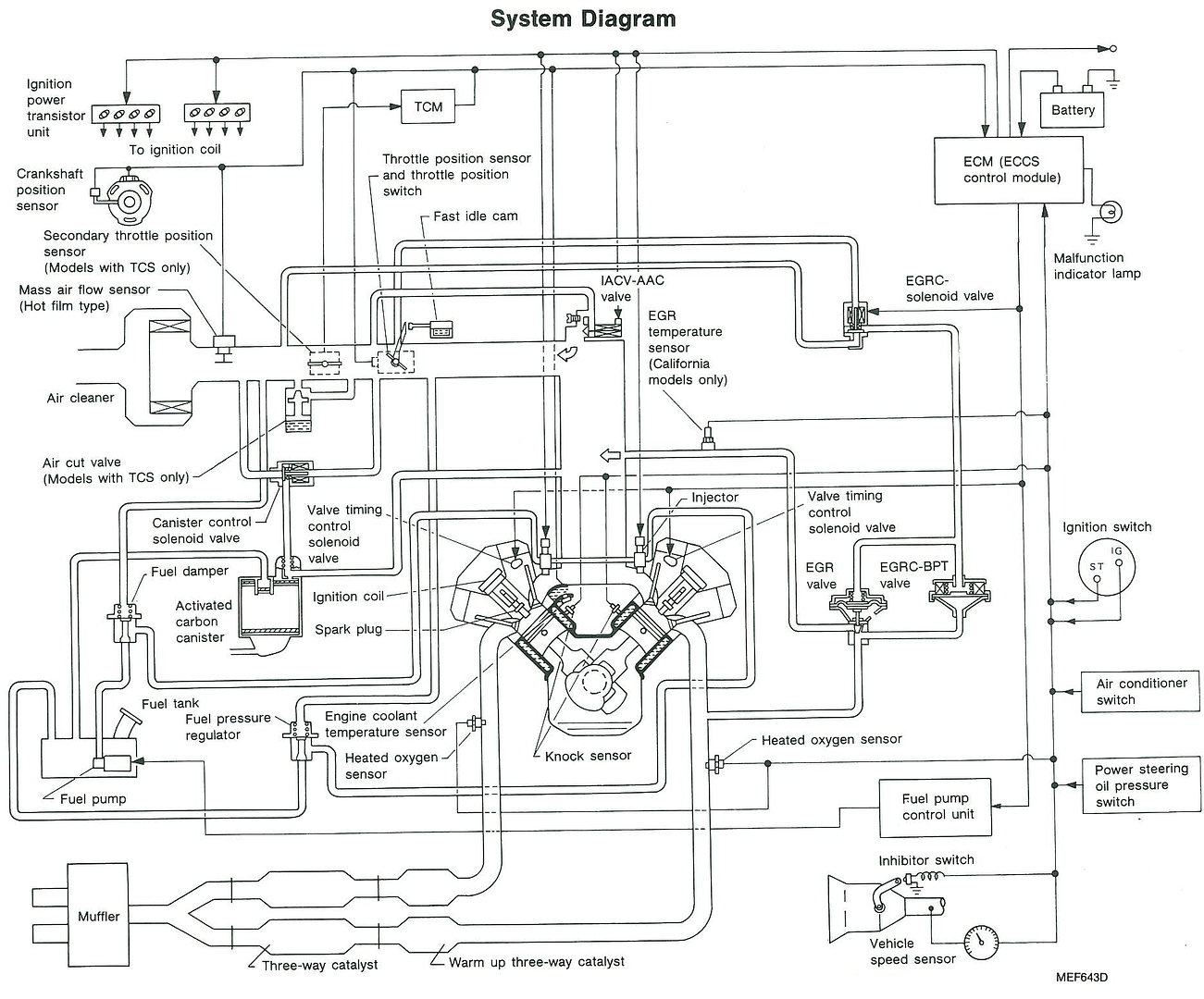
These first few images are for reference. If you're not all ready familiar with what's under the intake manifold or how the VH operates, this is a good place to start. The first image displays the component layout. The second shows an exploded view of most of the components we'll be addressing. The third one shows the majority of the vacuum routing. The fourth image illustrates how the control systems are related to and effect each other.
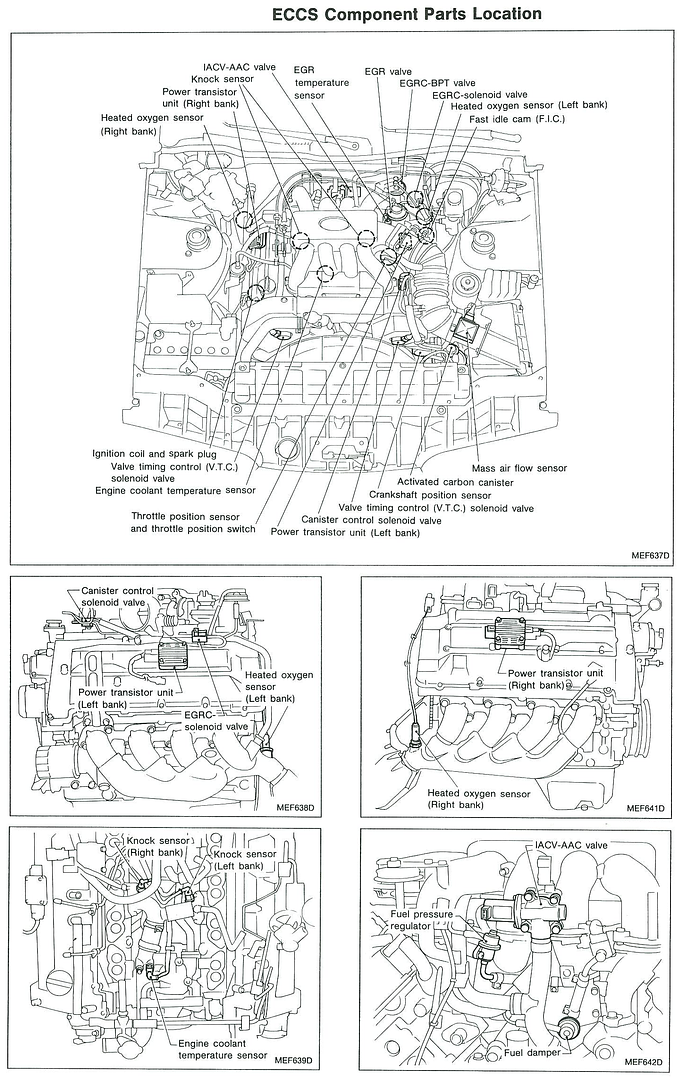
As we look at the following systems/components, I'll explain where they are, what they do, and how to address them. I've also pieced together information that I gathered from different sections of the FSM that are related to that particular topic. It's just additional details that you may or may not find useful. I figure this will save you a lot of time digging through the FSM.
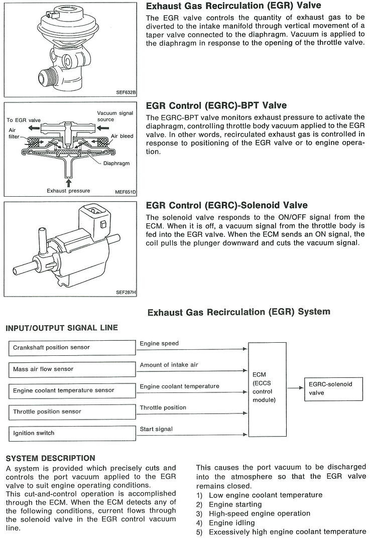
Exhaust Gas Recirculation (EGR)
This is located on the left side of the intake manifold behind the throttle body. The system consists of a valve, two diaphragms, and a tube connecting to the left exhaust manifold. The purpose of this system is to circulate some exhaust gas into your intake manifold. It reduces emissions by reducing the amount of oxygen available for combustion. Removing this system will reduce clutter at the back of the intake manifold and will marginally reduce the gunk in the intake manifold. Removing this system is necessary for most swaps or when using aftermarket headers as there are not usually provisions for the recirculation tube. Removing this system will add pollution to the atmosphere and you will likely fail emissions testing.
There are a couple options here. First is complete elimination. You'll need to install a block plate on the EGR flange ($10 from Mazworx if you don't want to make your own) with a new gasket or gasket maker and some shorter bolts. If you've still got the factory exhaust manifold, you'll also need to plug the bung hole with an M24x1.5 plug (oil drain plug from local parts store or whatever).
The other option is to just block the exhaust gas flow. The super cheap option is to simply install a nickel inside the fitting where the tube connects to the valve. The stealthy approach is to install a block plate under the valve and reassemble. I would recommend a gasket on either side of the plate to ensure it doesn't leak when you're done.
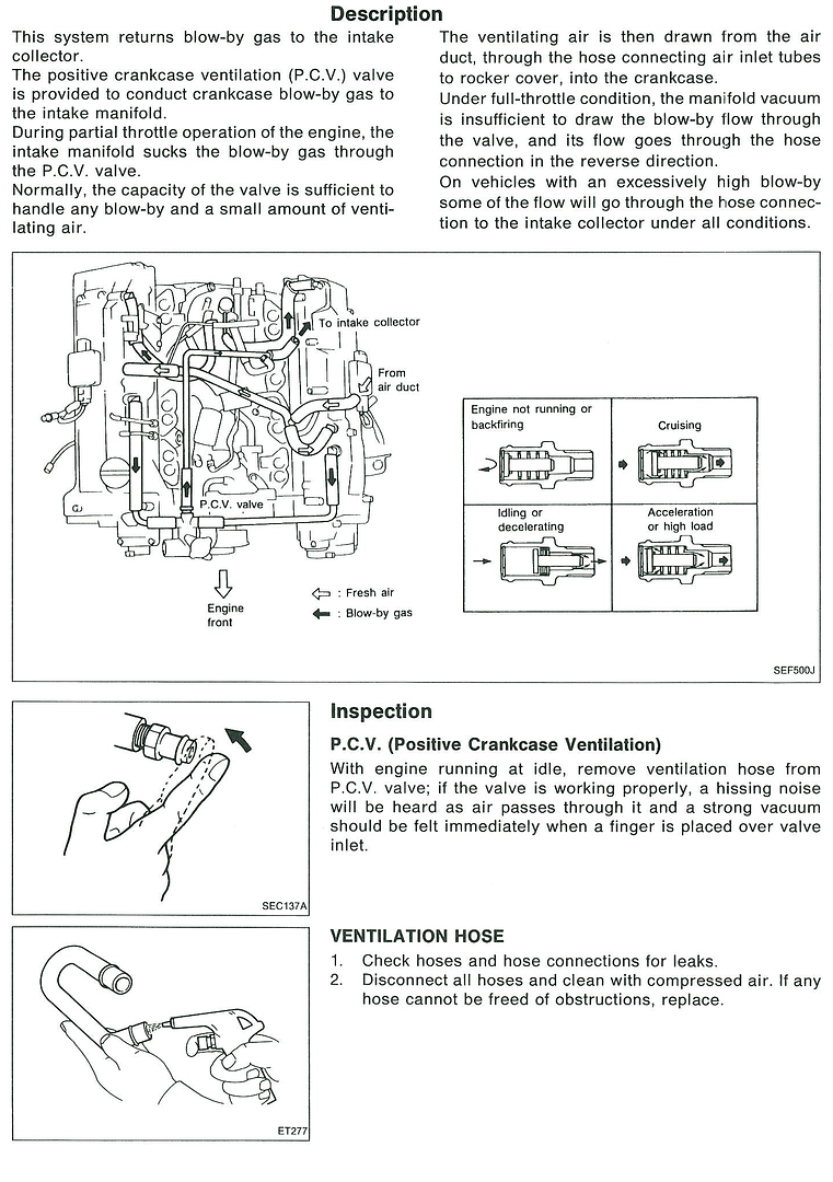
Crankcase Emission Control System - better known as Positive Crankcase Ventilation (PCV)
The plumbing for this system occupies space between the valve covers and under the intake manifold. The PCV valve is located on the filler neck of the thermostat housing in the front of the engine. There are three nipples on each valve cover (two large ones toward the front and one smaller one near the back). The smaller ones in the back connect to a fitting on top of the engine block. The middle nipples connect to each other via a pipe under the intake manifold and tee into the air intake. The front nipples attach to pipes on the front of the engine that tie in with the PCV valve at the filler neck. From the PCV valve, it is then routed through another pipe to the manifold behind the throttle body. The PCV is a check valve that should only allow flow into the intake manifold when functioning properly.
The purpose of this system is to return blow-by gases from the combustion process back to the intake manifold to be combusted again. The blow-by is a nasty concoction of water vapor, partially burnt gasoline, partially burnt oil, and some other combustion by-products. This system also serves as a means of removing oil particulates that get entrained in the crankcase from various moving parts sling and splash oil at tremendous speeds. There are baffles within the valve covers that are supposed to collect “condensed” oil and return it to the oiling system. Under most conditions, the vacuum of the intake manifold is sufficient to keep everything circulating; but under heavy load, the crankcase pressure can be greater than intake vacuum and back flow through the lines to the air intake.
The PCV system is the main source of the gunk inside the air intake and throughout the intake manifold. The hoses are also very difficult to deal with during maintenance as they wrap around intake runners and through other small spaces. These hoses are also very likely to be brittle and crack easily which ultimately causes intake leaks and poor engine performance. Most of the hoses are pre-bent and or have diameter changes – both of which make replacement difficult and/or expensive.
Modifying this system can become tricky – especially when positive intake pressures (boost) are introduced. How you go about dealing with this system is dependent on how the engine will be used and how much effort you’re willing to put in to keeping your intake clean. It helps to have a good understanding of how the system works. In any case, the best solution involves the use of a catch-can – either ventilated or sealed. For anything but a dedicated race engine, I believe that the best solution is to install a sealed, baffled catch-can between the PCV valve and the intake manifold. This will greatly reduce the amount of sludge pulled into the intake manifold while maintaining the functionality of the system. On a boosted setup, careful consideration must be taken to ensure that crankcase pressures don’t become so great that the dipstick becomes the pressure relief as that leads to a big mess and the risk of fire.
For an engine that spends most of its time under heavy load or for people who want to do this the easy way, a vented catch-can (sometimes called a breather tank) is usually the best solution. With this setup, it’s as easy as routing hoses to the catch-can and plugging the intake manifold and air intake. The issue with doing it this way is that when the engine isn’t under heavy load, there is no vacuum to provide circulation through the system as it only relies on positive pressure of the crankcase to evacuate the blow-by and oil particles. For someone taking the easy route that spends a lot of time cruising and idling, this will cause all of that sludge to be deposited in the crankcase and under the valve covers.
Modifying this system should not affect emissions testing. However, running a vented catch-can will pollute the atmosphere.
While we’re discussing this system, consider whether or not you will have to modify the thermostat housing. Some engine swaps necessitate the removal of the upper portion of the thermostat housing which includes the filler neck and PCV valve. This service can be provided by Performance VH or any competent aluminum welder. In order to maintain the original function of this system, it will be necessary to add a tee fitting for the front valve cover nipples and a way to include a PCV valve.
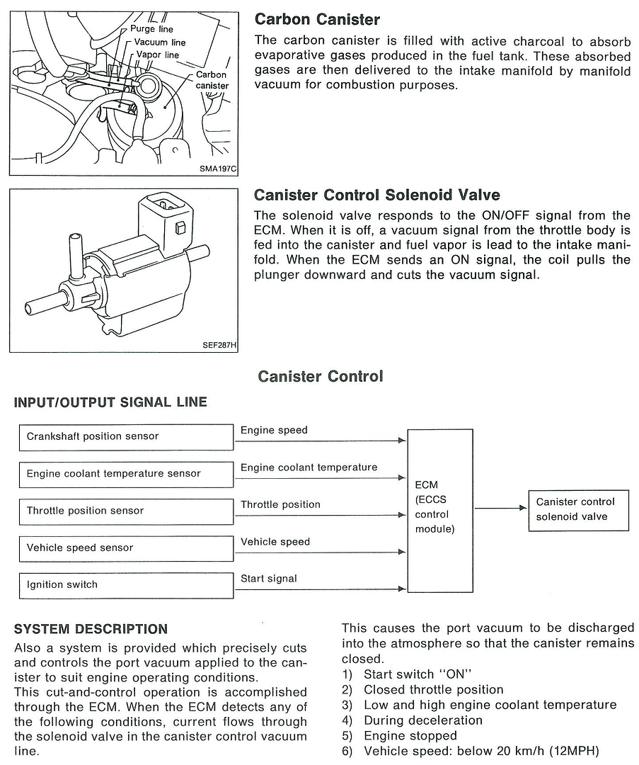
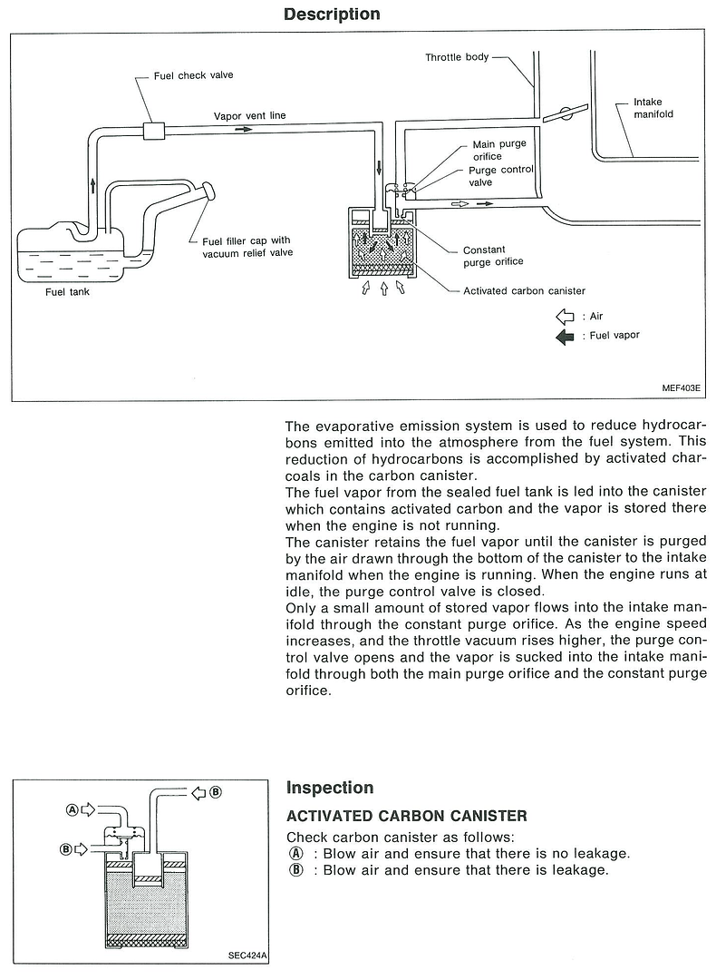
Carbon Canister
The Carbon Canister is located behind the left headlight near the bottom of the air filter housing on a Q45. It is in a similar location on the S13, S14, and Z32 as well. The system consists of a cylindrical container filled with activated charcoal. There is a purge valve on top of the canister which is controlled by an actuator. There are several hoses on the front left of the engine that go between these components and also a hose that comes from the fuel tank. The purpose of this system is to collect evaporating fuel from the fuel tank and send it to the intake manifold to be combusted.
The only reason to remove this system is to remove clutter from the engine bay. Even when doing an engine swap, the components on the engine could easily be adapted to fit the car’s carbon canister as it is simply a matter of re-routing a couple small hoses. Although there should be a check valve somewhere between the canister and the fuel tank, provisions should be taken to ensure that the vent line is routed in a way to prevent moisture and water from filling it. Bear in mind that not addressing the open line from the fuel tank could be hazardous if sparks or flames are used in an area that is not well ventilated. I would suggest removing the line as far back as the check valve or removing the entire line and capping it.
Modifying this system should not affect emissions testing, but you will likely pollute the atmosphere.
Catalytic Converters
The Q45 has four catalytic converters – one at the end of each header and two near the tail of the transmission. These converters use fancy chemistry to convert a lot of nasty exhaust gases into water vapor and inert gases like 02 and N2. For most engine swaps, the factory units are already gone long before the engine gets repurposed. If you still have them, removing them will aid in exhaust flow - especially when the converters are old and become fouled or the internal structures degrade.
The catalytic converters substantially reduce emissions from cars. Removing them will absolutely cause you to fail emissions testing. It is highly recommended that you install an aftermarket converter on your car – even if you’ve done an engine swap. Even in states where they don’t do emissions testing, police officers can do impromptu inspections during routine stops and issue citations because they are required by federal law. There are “high flow” catalytic converters available for racing applications that are reasonably priced. Almost all legitimate racing sanctioning bodies require functioning catalytic converters. Even so, anything short of OE equivalent replacements may not be enough to pass emissions testing.
There is no detailed information in the FSM regarding catalytic converters.
Idle Air Control Valve/Auxiliary Air Control Valve (IACV-AAC)
The IACC-AAC is located at the back of the intake manifold in the middle. The controller is plumbed to the air intake and the regulated air is plumbed behind the throttle body and underneath the manifold. There is also a Y-pipe on the line between the air intake and the IACV. The third branch attaches to a tube that runs in the valley of the block and attaches to the thermostat housing where it dead ends. The purpose for this tube is unclear, but I suspect it has something to do with NVH cancellation. My best hypothesis is that it works like a shock arrester similar to what you would find on water plumbing near faucets.
The IACV-AAC is crucial in maintaining idle. It is possible to function without it; but for a car that’s driven regularly, it would be a nuisance. Xcessive Manufacturing makes a relocation kit if you want to reduce clutter or make a custom intake manifold. At the very least, I would recommend getting rid of the resonator tube and the Y-pipe and replace the hoses.
Modifying this system should not affect emissions testing.
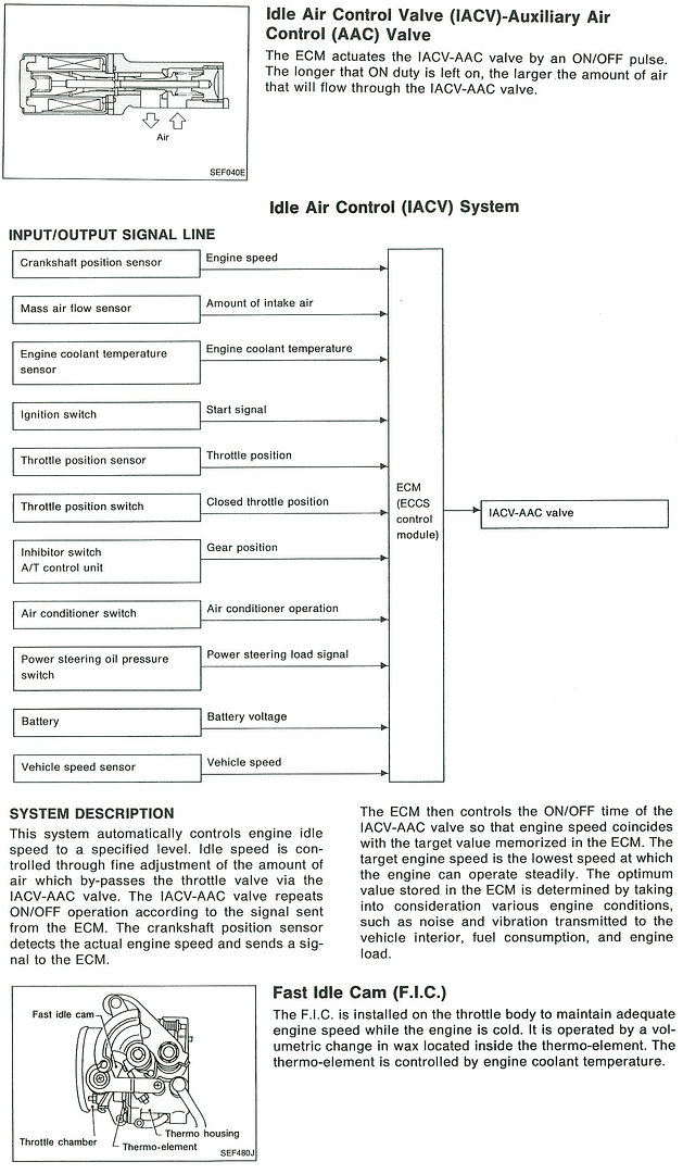
Fast Idle Cam
The fast idle cam is on the side of the throttle body. It adjusts throttle position based on engine temperature and is the reason there are coolant lines running through the throttle body. As the engine warms up, the coolant heats wax inside a thermo-element which then activates the cam. This can be bypassed for the sake of removing clutter under the intake manifold by re-routing the feed and return lines, or they can be removed and capped at the supply and returns.
If you plan on driving the vehicle regularly in a climate that is not warm, you could be inconvenienced by modifying this system. Modifying this system should not affect emissions testing.
Since the FIC is closely related to the IACV-AAC and there wasn't much additional information about it in the FSM, I included it above.
I believe this addresses everything that could be modified for the sake of simplification under and around the intake manifold. I hope someone will find this information useful. Once I've completed the modifications on my Q, I'll come back and share some more information and updates.