SOHO Motorsports Single Turbo Kit
2003-2007 Nissan 350Z and Infiniti G35, VQ35DE Engine
Available for Purchase Late Summer 2012
http://www.sohomotorsports.com
SOHO Motorsports Single Turbo Kit The Design:
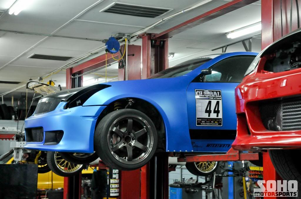
With Momentum Performance having to close its doors earlier this year, the industry was left with a vacancy for a single turbo kit for the 350Z/ G35 community. After competing in numerous track days from regional NASA events all the way up to Global Time Attack events with the Momentum Performance turbo kit on our SOHO Motorsports G35. Over more than a 16 month period of unebelievably hard abuse on the car, we were able to discover a few items that needed to be changed in order to help increase the efficiency and performance of this kit. With all of the knowledge we posess of motorsports, the owner of SOHO and head tuner is Nik Sohoritis. With his former NASCAR engineer expertice and knowledge of mechanical engineering, Nik has calculated everything for this turbo kit to ensure that it will be one of the most efficient turbo kits in the market. From the flow of the air via new routing of pipes to the efficiency of the intercooler. Throughout this article we will be discussing the basics of the turbo kit from the choice of turbo, intercooler and cold side piping and the reasons we are doing what we are doing with calculations that describe to you why we have chosen these items.
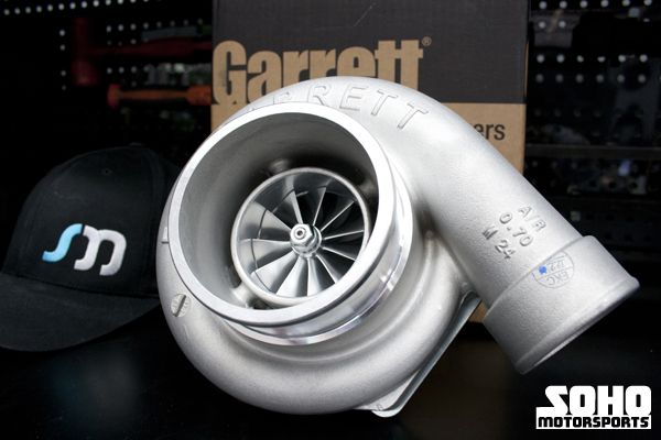
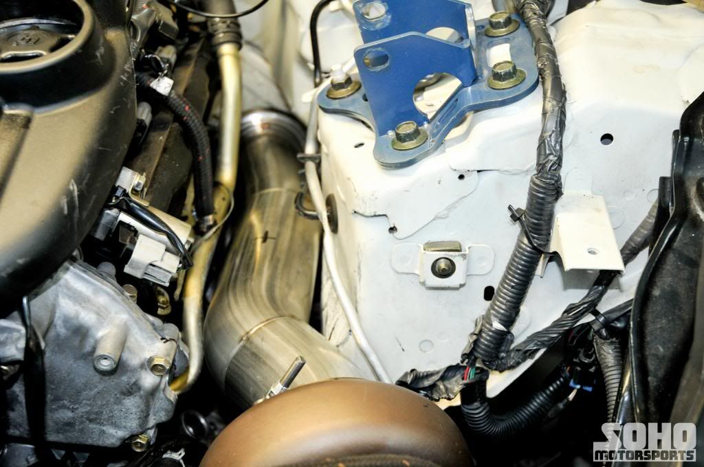
The Turbo:
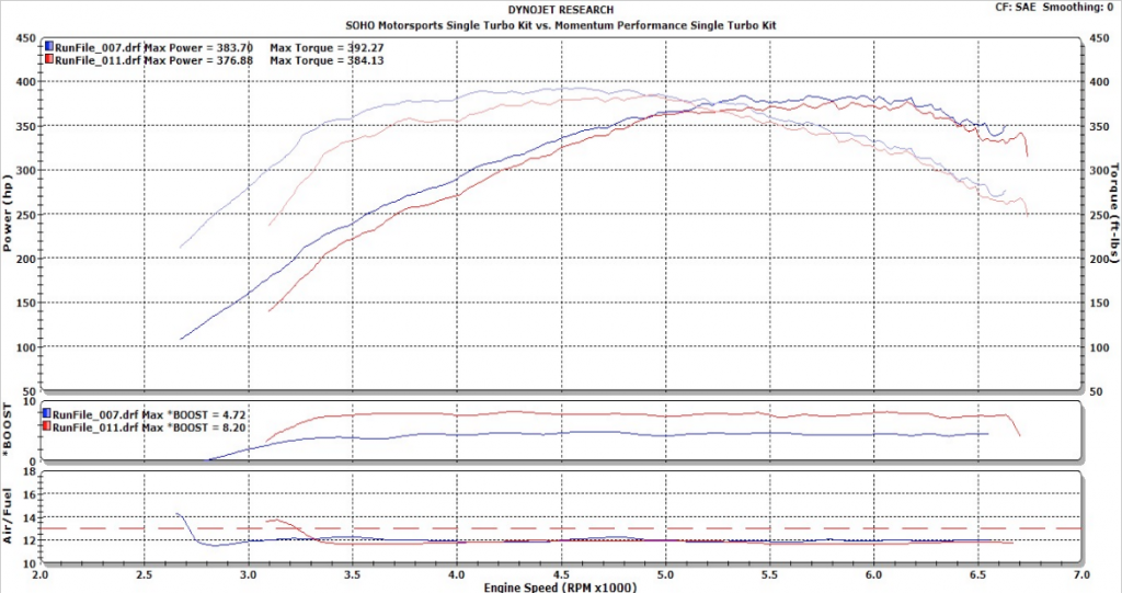
Before we begin I must note that our kit is in no way based off of or uses anything similar to the Momentum turbo kit, but for sake of reasoning we will be using that to compare to ours in this article because of its popularity as one of the best single turbo kits for the Z and G platform. The Momentum Performance turbo kit utilized the Garret GT3582R turbo with a 1.03 A/R custom Tial turbine housing. This created a very linear power curve from 3500 to 6800 rpm on any VQ35 motor with a compressor efficiency ranging from 74 to 75 percent at a boost level of 9 psi throughout the power curve. When comparing the GT3582R and the all new GTX3582R, which we will be using for SOHO kit, the inducer is 0.05 inches larger in diameter and the exducer is .02 inches larger in diameter for the GTX3582R. This results in a slight increase in airflow and a larger trim. In the single turbo kit that we are designing and building, we have chosen the all new Garret GTX3582R turbo with a Tial 1.06 A/R turbine housing that will have an increase in compressor efficiency throughout the power band by at least one to two percent. With this increase in efficiency the compressor is pumping air to a point where the air is not getting heated more than it should be, based on the pressure ratio, thus resulting in cooler and denser air into the intake system and in turn yielding more power. The Tial turbine housing that we have chosen incorporates a slightly higher A/R ratio that will bring a smoother transition into boost and will allow for more exhaust gases to flow in the higher rpm range with less restriction.
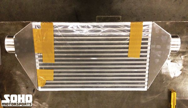
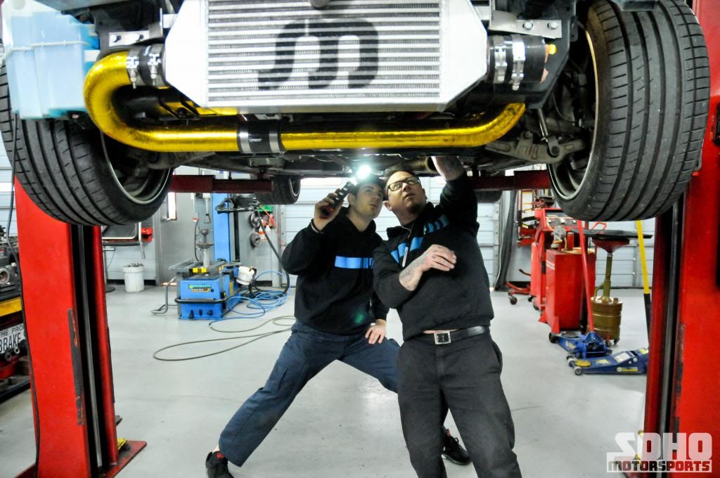
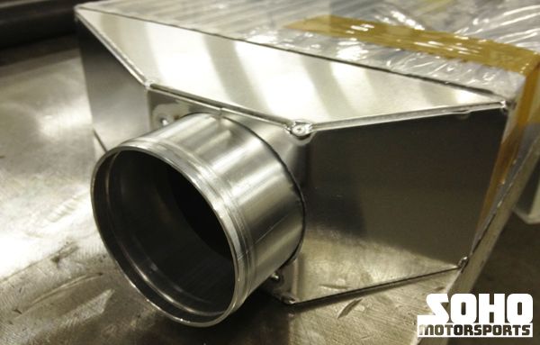
The Intercooler:
In the design process of an intercooler there are two essential characteristics to consider in creating an efficient inercooler as possible; internal flow area and frontal core area. The internal flow area of an intercooler core can be determined by multiplying the core length, core height, and the number of cooling air channels in the core. Both of the intercoolers, for our turbo kit and the Momentum Performance turbo kit are using the plate and shell style intercooler core. A rule of thumb to always follow is that when the internal flow area of an intercooler core is large, the pressure loss through the core will be small. The difference with the intercooler that we have chosen for the SOHO Motorsports single turbo kit is that we have increased the overall height and thickness of the core and decreased the length. After a few calculations we were able to determine the intercooler core that we were going to use for our turbo kit when compared to the Momentum intercooler had almost an eighteen percent drop in overall pressure loss. Once we had determined the core size for the intercooler we shifted our attention over to the end tank design, where we found that the two inch end tanks on the Momentum intercooler were not going to be sufficient enough in creating a system that minimized pressure loss. We increased our end tanks by almost a full inch on both sides and decreased the angles for the inlets to allow for the air to travel in a more uniform and less turbulent manner.
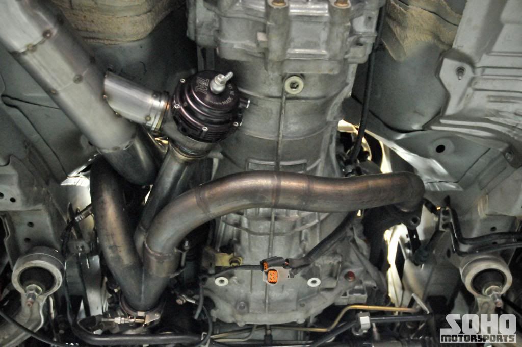
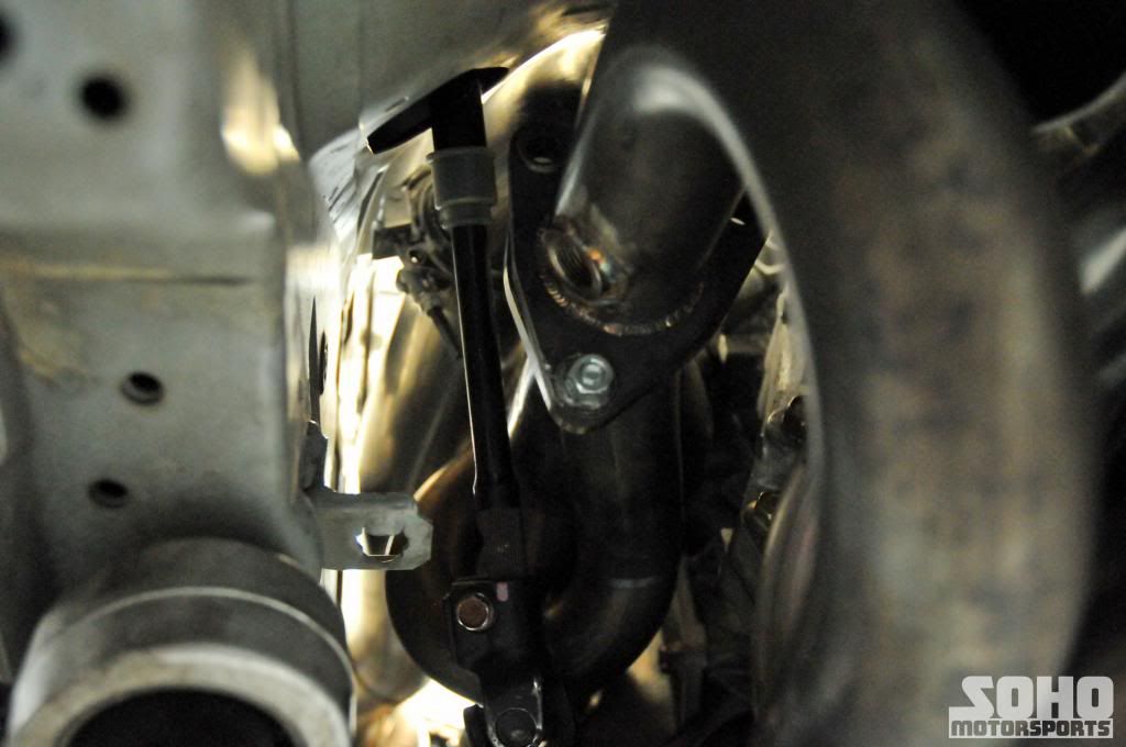
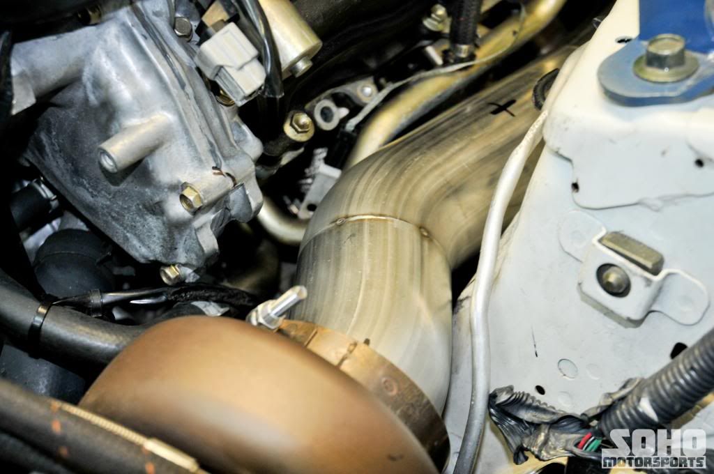
The Piping:
Many hours were spent in determining the best way to route the cold side piping for our turbo kit, and once we determined the routing we were able to see a huge benefit compared to the current setups on the market today. The current single turbo kit takes the charge air coming out of the turbo and goes thru the intercooler, up along the topside of the radiator and then into the intake manifold. There is a problem that occurs when routing the cold side piping this way, in that you are heating all of the air going into your throttle body after you have cooled in the intercooler, since the intake pipe is sitting on top of the radiator in stagnant heat within the confines of the engine bay. We have completely avoided this path and have decided to take the charge air coming from the turbo and route the piping in between the radiator and sway bar on the bottom side of the vehicle, to where it would come into the intercooler from the passenger side and out the driver’s side and straight into the intake manifold. With the charge pipe being run close to the bottom of the vehicle, the air that travels underneath the vehicle and under this pipe will help in slightly reducing heat soak of the air before it travels into the intercooler, thus creating a somewhat pre-intercooler cooling system. Along with the re routing of the traditional single kit to the bottom we also have increased the overall diameter for the cold side which has been calculated to withstand airflow for up to 800 horsepower (1200 cfm) before there would be any pressure loss in the pipe from the air traveling at speeds higher than Mach 0.4 (400 ft/s).
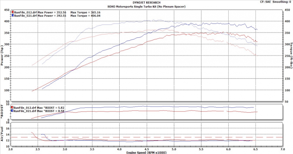
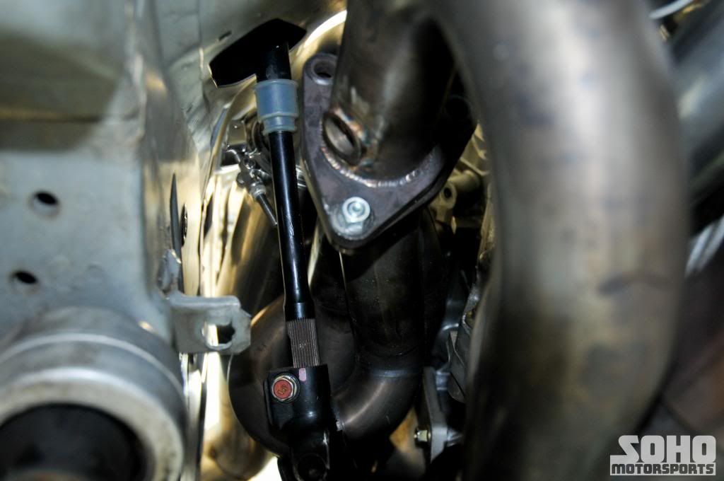
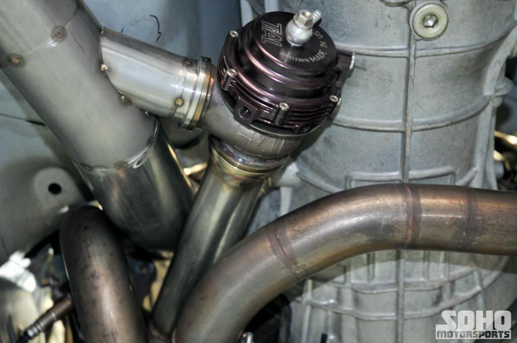
Stay tuned as we discuss the routing of the exhaust side of the piping and determine which type of waste gate and blowoff valve we are going to use (diaphragm based or pneumatic piston based). Plus we will be updating with all dyno and track results.