Need a KA guy to run a simple test for me
-
Jmoore124
- Posts: 278
- Joined: Wed Dec 12, 2012 4:22 pm
- Car: 1995 240sx Ka-t
2003 Saab Linear turbo conv
(Sold) 1989 S13 red top
Need a KA guy to run a simple test for me
So this may seem like a moronic question. I have had a feeling I have a electrical issue for a while now. My positive feed for the engine fuse box has continuity to ground. Before I start unplugging and pissing myself off, can somebody else with a KA run a continuity check on their fusebox for me? I am testing from the bolt like terminal on the back drivers side of the main engine relay/fuse box. Appreciate it. 
-
pepesilvia

- Posts: 584
- Joined: Tue Feb 21, 2012 8:15 pm
- Car: 96 S14
- Location: New Jersey :(
Re: Need a KA guy to run a simple test for me
i'm really bad with electronics, but if you run me through it step-by-step and what exactly you're looking for i'll do it for you. 
-
Jmoore124
- Posts: 278
- Joined: Wed Dec 12, 2012 4:22 pm
- Car: 1995 240sx Ka-t
2003 Saab Linear turbo conv
(Sold) 1989 S13 red top
Re: Need a KA guy to run a simple test for me
I really appreciate it Pepe, its really simple.
All you need to do is get a voltmeter, turn it to the 'Ohms' Setting (Its the little horseshoe thing with the coil on the end) Open the fuse/relay box under the hood, put one lead on the Bolt where the power is supplied to the box (has a nut on top) and then the other lead of the voltmeter on your batteries negative terminal. If you have continuity it will show you a value, or beep. If not there will be letters like 'OD' on the screen.
All you need to do is get a voltmeter, turn it to the 'Ohms' Setting (Its the little horseshoe thing with the coil on the end) Open the fuse/relay box under the hood, put one lead on the Bolt where the power is supplied to the box (has a nut on top) and then the other lead of the voltmeter on your batteries negative terminal. If you have continuity it will show you a value, or beep. If not there will be letters like 'OD' on the screen.
-
pepesilvia
- Posts: 584
- Joined: Tue Feb 21, 2012 8:15 pm
- Car: 96 S14
- Location: New Jersey :(
Re: Need a KA guy to run a simple test for me
First i would like to apologize for my breathing in this video, I had the gopro in my mouth and didnt realize i was breathing all over it. Its pretty obnoxious at first hahahaha
[youtube]http://www.youtube.com/watch?v=sOR_aC81 ... e=youtu.be[/youtube]
I'm not sure if i did this right, but it beeped at 200 and 2k and had the number "1" on the entire time. It flashed numbers for split second only when i was taking it off when it was on 20k.
if you want me to do it again or do something different then let me know.
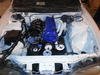
ALSO, ignore the red wire coming off the negative terminal on the battery, its the only wire i had, but i assure you its the negative terminal.
[youtube]http://www.youtube.com/watch?v=sOR_aC81 ... e=youtu.be[/youtube]
I'm not sure if i did this right, but it beeped at 200 and 2k and had the number "1" on the entire time. It flashed numbers for split second only when i was taking it off when it was on 20k.
if you want me to do it again or do something different then let me know.
ALSO, ignore the red wire coming off the negative terminal on the battery, its the only wire i had, but i assure you its the negative terminal.
-
Jmoore124
- Posts: 278
- Joined: Wed Dec 12, 2012 4:22 pm
- Car: 1995 240sx Ka-t
2003 Saab Linear turbo conv
(Sold) 1989 S13 red top
Re: Need a KA guy to run a simple test for me
Haha that's awesome! 
You definitely did It right. But not being familiar with your multimeter I cant tell exactly what settings you have it on.
So basically you switch the dial to this symbol http://www.bing.com/images/search?q=ohm ... tedIndex=1
Some multimeters will have multiple symbols for resistance, but you want the standard setting like in this picture (if it has one) and what you are testing for is a circuit path (continuity)
So a control test for your multimeter would be to find this setting, and connect the two leads to each other(red probe to black probe).
Whatever it does when you do this test would be what to expect when you have low resistance, or a proper circuit. So if it did the same thing when you connected it to the battery/relay box as it did on the bench test, that tells me exactly what I was looking for.
It looked to me like I was just worrying myself. Judging by what I saw yours does the same thing as mine. I was just concerned that the positive terminal on the relay box was grounded..But I guess it would have to be to be a complete circuit..
-
pepesilvia
- Posts: 584
- Joined: Tue Feb 21, 2012 8:15 pm
- Car: 96 S14
- Location: New Jersey :(
Re: Need a KA guy to run a simple test for me
the dial on my multimeter has a lot of different choices for ohms. i was just switching between all of them because i wasnt sure which ohm setting was right...

^^^ mine kind of looks like this multimeter's dial. it says "200, 2k, 20k, 200k, 2m, 20m, 200m". when i put it on 200 ohms and 2k ohms it would beep.
I bought the multimeter a long time ago and this was the first time i used it haha. thanks for the lesson though, I'm always ready to learn a few things.