How to: Set up your PCV, Catch Can, Breather, Vacuum system on your RB...
-
amakadius
- Posts: 250
- Joined: Mon Mar 31, 2008 9:05 pm
- Car: 1995 nissan 240sx rb25det S14.5 conversion
- Contact:
Re: How to: Set up your PCV, Catch Can, Breather, Vacuum s ... (Coolwhip)
thank you for this posting cool whip
-
SullivanRacing06
- Posts: 1974
- Joined: Sat Apr 21, 2007 8:45 am
- Car: r32 gtst, 06 350z, r32 gtr, rs4 steaga, 04 350z, f350/6bt
- Location: Gainesville
OK i got the greddy can, I got the summit kit with the 2 valves. Is it sufficient for me to run both of the hoses from the 2 valve cover ports into the can and one line into the downpipe or should i run 2. In other words is one line into the downpipe going to provide sufficient vaccum for the can.
Now both of the ports on the valve cover are 90 degrees with one side conneting the 2 ports and one going to the the pcv and one going god knows where (RB26) Is there a part number for a block off for these ports? How do I block off the pcv?
Thanks
Now both of the ports on the valve cover are 90 degrees with one side conneting the 2 ports and one going to the the pcv and one going god knows where (RB26) Is there a part number for a block off for these ports? How do I block off the pcv?
Thanks
-
Darius
- Posts: 4820
- Joined: Sun Mar 02, 2003 9:48 am
- Car: RB25DET S14 - 665 WHP (SOLD)
- Location: Chicagoland
Re: (sr20tom)
One hose to the exhaust to pull vacuum is good...two is better.
You can block off the PCV port by tapping the hole and inserting an NPT plug.
You can block off the PCV port by tapping the hole and inserting an NPT plug.
Re: (Darius)
1/2 inch NPT works with out drilling into the valve cover pcv port...
-
HxC_Nismo

- Posts: 1036
- Joined: Sat Sep 23, 2006 10:26 am
- Car: '98 Nissan 240SX SE R33 RB26DET
'07 Nissan Titan SE
'05 Toyota Corolla - Location: Missouri
- Contact:
Re: (Coolwhip)
is it necessery to have two valves instead of just one cause on my new setup i was thinking of blocking off the pcv and putting an fittings into the valve covers that go to the catch can and one fitting on the catch can that will go into the check valve into the downstream exhaust. also do the factory fittings on the valve covers screw out?Coolwhip wrote:Compliments from Sullivan...
His EVAC to downpipe dump setup...
-
Darius
- Posts: 4820
- Joined: Sun Mar 02, 2003 9:48 am
- Car: RB25DET S14 - 665 WHP (SOLD)
- Location: Chicagoland
Re: (HxC_Nismo)
You do not need separate lines to the exhaust. One tube will still pull vacuum on each valve cover if they're interconnected at the catch can.
The fittings in the valve covers are just press fit. I used a large adjustable wrench and wiggled it back and forth until it came up. Then I tapped since the openings happened to be perfect for a 1/2" NPT if I remember correctly. Double check that because it was over a year ago that I did that.
Modified by Darius at 10:42 AM 2/2/2010
-
SullivanRacing06
- Posts: 1974
- Joined: Sat Apr 21, 2007 8:45 am
- Car: r32 gtst, 06 350z, r32 gtr, rs4 steaga, 04 350z, f350/6bt
- Location: Gainesville
Re: (Darius)
the 26 valve cover nipples are pressed in, i ran 2 bc i was thinking the more the better, oh well, im attempting to buy a r32 gts-t and im planning on switching my 26 w 25 transmission in the gts-t n using my caged s13 as a track only car.
-
SullivanRacing06
- Posts: 1974
- Joined: Sat Apr 21, 2007 8:45 am
- Car: r32 gtst, 06 350z, r32 gtr, rs4 steaga, 04 350z, f350/6bt
- Location: Gainesville
Re: (Coolwhip)
be interested in seeing the "new set up"
-
SullivanRacing06
- Posts: 1974
- Joined: Sat Apr 21, 2007 8:45 am
- Car: r32 gtst, 06 350z, r32 gtr, rs4 steaga, 04 350z, f350/6bt
- Location: Gainesville
Re: (SullivanRacing06)
any new set ups come around?
bringing this back from the dead..
im pulling my motor to clean some stuff up but im redoing my set up as well,
bringing this back from the dead..
im pulling my motor to clean some stuff up but im redoing my set up as well,
Re: (SullivanRacing06)
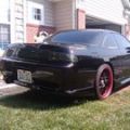
heres mine, its baffled and reciculated back into the turbo
Its all -10 i didnt have the lines routed yet but you can see the fittings coming out of the valve cover (1/2in NPT)
Its all -10 i didnt have the lines routed yet but you can see the fittings coming out of the valve cover (1/2in NPT)
-
l0nestar
- Posts: 2251
- Joined: Fri Mar 10, 2006 5:24 am
- Car: 1993 Nissan 250SX
2004 Toyota Altezza
1963 Chevy Impala SS - Contact:
Re: How to: Set up your PCV, Catch Can, Breather, Vacuum sys
Here are my two options that I am debating between. Behold my awesome MSPaint skillz.

Basiclly,
Figure 10 is tying the intake and exhaust rockers together, and utilizing the OE PCV valve, and connecting to one of the taps on my Greddy IM.
Figure 11 is utilizing a sealed catch-can (with internal baffling) and using the intake pipe (post MAF) for vacuum source while capping the OE PCV valve.
Is there anything wrong with my designs (theoretically, speaking)? With both of them am I going to be drawing mostly from one rocker or the other? Should I modify figure 11 to have dual feeds going into the catch-can, instead of the single?
So far my rockers and MAF tube are tapped 3/8 PT. As far as hardware, I'm looking at -6 or -8AN fittings and hoses (probably -6).
-
SullivanRacing06
- Posts: 1974
- Joined: Sat Apr 21, 2007 8:45 am
- Car: r32 gtst, 06 350z, r32 gtr, rs4 steaga, 04 350z, f350/6bt
- Location: Gainesville
Re: How to: Set up your PCV, Catch Can, Breather, Vacuum sys
yes you can run one in one out of the catch can, thatll a fine set up bc itll get vac under boost were its important
-
Darius
- Posts: 4820
- Joined: Sun Mar 02, 2003 9:48 am
- Car: RB25DET S14 - 665 WHP (SOLD)
- Location: Chicagoland
Re: How to: Set up your PCV, Catch Can, Breather, Vacuum sys
l0nestar, go with Fig 11. Fig 10 is incomplete since the PCV valve will be closed under boost and the block will pressurize with blow-by gases. Either add the catch can and lines like you show in Fig 11, or just install the system like Fig 11.
flatrate, I love your entire setup BTW! Looks clean as hell! Your catch can makes me wish I had a TIG and your skills. Maybe Santa will be good to me this year
flatrate, I love your entire setup BTW! Looks clean as hell! Your catch can makes me wish I had a TIG and your skills. Maybe Santa will be good to me this year
-
SullivanRacing06
- Posts: 1974
- Joined: Sat Apr 21, 2007 8:45 am
- Car: r32 gtst, 06 350z, r32 gtr, rs4 steaga, 04 350z, f350/6bt
- Location: Gainesville
Re: How to: Set up your PCV, Catch Can, Breather, Vacuum sys
fig 11 is correct
fig 10 would pressurize the block under boost as darius said
fig 10 would pressurize the block under boost as darius said
-
ST240
- Posts: 575
- Joined: Sun Aug 04, 2002 11:45 am
- Car: RB30DET Nissan S13
'01 Nissan Pathfinder - Location: Edmonton, Canada
Re: How to: Set up your PCV, Catch Can, Breather, Vacuum sys
Wait a tick, Why did he block that off in Fig 11?SullivanRacing06 wrote:fig 11 is correct
fig 10 would pressurize the block under boost as darius said
Why is that better than leaving it plumbed to the intake manifold (Fig 1) via OEM PCV and just putting the catch can "inline" from the valve covers to the pre turbo intake pipe (ie nearly identical to original Figs 3 and 4)?
All of the original setups that Coolwhip posted show the OEM PCV intact when using the pre turbo intake pipe as the vac source.
Thats what I was gonna do, now I'm confused
-
Darius
- Posts: 4820
- Joined: Sun Mar 02, 2003 9:48 am
- Car: RB25DET S14 - 665 WHP (SOLD)
- Location: Chicagoland
Re: How to: Set up your PCV, Catch Can, Breather, Vacuum sys
The OEM PCV is there to minimize the amount of oily vapor running through the intake piping and intercooler. Most of the time the car is not under boost, so vacuum is being pulled directly into the intake manifold. It isn't a necessary element to the function of the system as long as it is modified appropriately.
Running a catch can between the valve covers and intake pipe attempts to achieve the same result.
Running a catch can between the valve covers and intake pipe attempts to achieve the same result.
-
ST240
- Posts: 575
- Joined: Sun Aug 04, 2002 11:45 am
- Car: RB30DET Nissan S13
'01 Nissan Pathfinder - Location: Edmonton, Canada
Re: How to: Set up your PCV, Catch Can, Breather, Vacuum sys
So which is better, using the OEM PCV w/ catch can to intake pipe/valve covers or with it blocked off?Darius wrote:The OEM PCV is there to minimize the amount of oily vapor running through the intake piping and intercooler. Most of the time the car is not under boost, so vacuum is being pulled directly into the intake manifold. It isn't a necessary element to the function of the system as long as it is modified appropriately.
Running a catch can between the valve covers and intake pipe attempts to achieve the same result.
-
primedirective
- Posts: 13
- Joined: Tue Mar 06, 2012 3:44 pm
- Car: S14
Re: How to: Set up your PCV, Catch Can, Breather, Vacuum sys
Sorry for bringing this back from the dead...
If the system from figure 2 is used then the valve covers will never see vacuum. Is this the worst set up? To me this system seems the simplest but what do I risk by not having the valve covers under vacuum?
If the system from figure 2 is used then the valve covers will never see vacuum. Is this the worst set up? To me this system seems the simplest but what do I risk by not having the valve covers under vacuum?
-
Coolwhip

- Vendor
- Posts: 3138
- Joined: Fri Feb 06, 2004 7:29 am
- Car: RB26 Raw Brokerage War Machine
- Location: Orlando, FL
- Contact:
Re: How to: Set up your PCV, Catch Can, Breather, Vacuum sys
The upside to having proper vacuum on the crankcase/valve covers is that it provides better sealing of the rings and valves. This obviously contributes to higher compression in the cylinders resulting in more power output.
Re: How to: Set up your PCV, Catch Can, Breather, Vacuum sys
not as good as the trunk monkey but thought i would pass it on
http://vibrantperformance.com/2012_cata ... e_pg64.pdf
http://vibrantperformance.com/2012_cata ... e_pg64.pdf
-
Duke89
- Posts: 29
- Joined: Thu Oct 07, 2010 8:33 pm
- Car: 11/88 cream yellow/gray two tone RB20 project
Re: How to: Set up your PCV, Catch Can, Breather, Vacuum sys
that's pretty good already has the check valve made in so just weld on hook you're hose to it and go.tacozzz wrote:not as good as the trunk monkey but thought i would pass it on
http://vibrantperformance.com/2012_cata ... e_pg64.pdf
-
Coolwhip
- Vendor
- Posts: 3138
- Joined: Fri Feb 06, 2004 7:29 am
- Car: RB26 Raw Brokerage War Machine
- Location: Orlando, FL
- Contact:
Re: How to: Set up your PCV, Catch Can, Breather, Vacuum sys
Actually, we have them in stock:
http://www.rawbrokerage.com/Vibrant-Sta ... VP1189.htm
It's the very part that I used on my S14.
http://www.rawbrokerage.com/Vibrant-Sta ... VP1189.htm
It's the very part that I used on my S14.
-
Duke89
- Posts: 29
- Joined: Thu Oct 07, 2010 8:33 pm
- Car: 11/88 cream yellow/gray two tone RB20 project
Re: How to: Set up your PCV, Catch Can, Breather, Vacuum sys
ill probably be ordering one in the near future then.. im liking the vibrant catch can too.
Re: How to: Set up your PCV, Catch Can, Breather, Vacuum sys
vibrant makes neat stuff, im using there 4in aluminum race muffler, love it so far
Re: How to: Set up your PCV, Catch Can, Breather, Vacuum sys
that's cool and all, but a sealed system is probably best. much more crankcase vacuum and you actually have a rough idea how much blowby you have when you empty the catch can.
Re: How to: Set up your PCV, Catch Can, Breather, Vacuum sys
on my new setup im using 2 -12's (1 on each valve cover) and running them right to the ground, I made my own baffling out of some stainless steel mesh stuff and stuffed it into the stock valve cover baffle plates it flows good still, no oil leaks or any kinda oil coming from the breather hoses yet... and im on 20psi with a 6766
Pulling a vacuum is cool, but overkill in most cases... people running 1000+ whp hondas with the above mentioned way of venting.
Pulling a vacuum is cool, but overkill in most cases... people running 1000+ whp hondas with the above mentioned way of venting.
Re: How to: Set up your PCV, Catch Can, Breather, Vacuum sys
i have figure 10 set up on mine; however, i do have a breather filter on the DS fitting. Would that cause any unmetering air?
I did tried to blocked off the line going from the PS fitting to the manifold, but smoke would come out of my exhaust when i drive occasionally, which led me to believe to turbo has a blown seal. I did have a look at the turbo compressor wheels, and its' dry, and spins freely.
I did tried to blocked off the line going from the PS fitting to the manifold, but smoke would come out of my exhaust when i drive occasionally, which led me to believe to turbo has a blown seal. I did have a look at the turbo compressor wheels, and its' dry, and spins freely.
-
Darius
- Posts: 4820
- Joined: Sun Mar 02, 2003 9:48 am
- Car: RB25DET S14 - 665 WHP (SOLD)
- Location: Chicagoland
Re: How to: Set up your PCV, Catch Can, Breather, Vacuum sys
figure 10 works if you open up one of the valve cover outlets basically turning it back into a stock setup.
The reason your car is probably smoking when you plug off the PCV line is because your filter is coated in oil and choking the flow of air out of the block. Remove the filter and it will go away. You can plumb in a catch can and run a line to the intake to pull vacuum on the system. Or just vent the catch can to atmosphere. Mine has a hose that just points to the ground. No filter.
The reason your car is probably smoking when you plug off the PCV line is because your filter is coated in oil and choking the flow of air out of the block. Remove the filter and it will go away. You can plumb in a catch can and run a line to the intake to pull vacuum on the system. Or just vent the catch can to atmosphere. Mine has a hose that just points to the ground. No filter.