Things you will need:
<> Assorted primary wire (10, 12, 14, 16, 18, 20ga)
<> 3 Inline Fuse Holders (2 12ga, 1 16ga approx.)
<> Electrical tape - several rolls (Duck or 3m; everything else sucks!)
<> Plastic Wire Conduit (Loom); I used 3/8", 1/2", 5/8", 3/4", and 1"
------ I used several feet re-wrapping ERH, ERH2, ECCS Harness, and Sub-Harnesses
<> Good wire strippers; I have Kronus automatic ones --> recommended!
<> Heat shrink; 3/8" and 1/2"; I also used 5/8" on battery cable terminals
<> Diagonal cutters/snips
<> Several (red and blue; male and female) quick disconnect terminals
<> Several (red, blue, and yellow) butt connectors
<> At least 2 ring terminals; I used yellow
<> White electrical tape & sharpie (I like to label things!)
<> Different color electrical tape (helped me identify matching ends in my jumper harness)
<> 2 SPST (single pole, single throw) Relays; Nissan Green or Blue
<> Gray 8-Pin Connector from KA Engine Harness (with as much wire as possible, >1.5m)
<> Brown 8-Pin connector from KA Engine Harness (with as much wire as possible, >1.5m)
Recommended to do; not covered here:
<> Map out the pins for your ECU. I don't find it necessary for my write-up and is not a required step for an identical swap. Knowing where each wire actually goes may help you better understand the process.
Procedure:
Here's a conversion layout to set the playing field:

I started by clipping the "to be used" wires from their respective connectors on the VH ECCS Harness. I crimped quick disconnects on each "to be used" wire and with the white electrical tape and sharpie I labeled each wire with it's destination and which connector it came from. Some of the connectors may have the same color wires as others; it is important that you can discriminate between them. For the destination, I labeled the system component and/or the color wire it connects to (made life simple).


After each wire was labeled, I separated them from the connectors (which will not be used).

Then I organized them according to their destination: KA White, KA Gray, KA Brown, and custom.

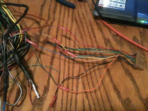
Next, I removed the Gray and Brown 8-pin connectors from the KA EFI Harness making sure to preserve as much of it's wiring as possible (at least enough for the length of your jumper; mine was approx 5 feet). I used a tiny flat head screwdriver and removed the unused wires from those connectors, pin and all - BUT I kept the removed wire just in case with the pin still attached. You will only need one instance of each wire left in your gray and brown connectors; therefore, removed all of the spliced wires as you see below: (Make sure you tape up each splice location.)


Crimp quick disconnects to the ends of each remaining wire making sure it is the opposite sex of the quick disconnects you used on the ECCS Harness. I added some heat shrink onto the end of each one and left it loose on the end so the opposite disconnect can fit right into the shroud it creates (as shown).


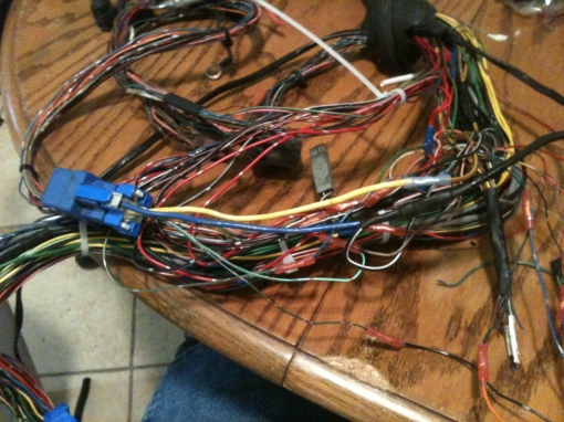
I mocked up the brown and gray harness along their path they way they would go. I zip-tied them together. This will be my jumper harness. I made a mark, using blue electrical tape, as to where my Custom Constant 12v power source with inline fuse can branch from the jumper to a 12v source. In my case, it will branch out at the location of my custom battery terminal -- where I ran power from the battery in the trunk to.


I used one of the 12ga inline fuse holders, crimped a ring terminal on the end and "butt" connected it to extend it back along the jumper through the firewall. As you notice in the picture, there are two wires coming back from the fuse holder; this is because I wanted a spare 12v constant power source inside the car in case I ever need it for something. I won't have to cut into the jumper or run anymore wires.


I tucked the jumper into some plastic loom. I identified where the "mark" of blue tape was and cut away a small piece of the loom to allow the wire to branch out. Then I tucked the 12v power wires into the loom as well.


I cut a full length piece of wire for the jumper to provide for the [Red -- 10amp (Ign=On/St)] wire from the blue VH connector. Tucked it in.


In order to accommodate an ignition coil relay (which the KA doesn't provide) some modifications have to be made. The Gray/Red wire that sends a signal to the ECCS relay and the Ignition Coil relay still must do so. Since the Ignition Coil relay will be under the dash by the computer, we must branch from the Gray/Red wire so that it can provide to both relays. It will provide to the ECCS relay via the Red/Black wire in the jumper, and now it will provide to the Ignition coil relay via the added branch. Crimp a quick disconnect female on the branch (required).


Using the same logic as above, we must branch the thicker Black/White wire from the blue connector of the VH ECCS Harness. The only difference is the direction of the signal in the wire. The Gray/Red send a signal from the ECU, the Black/White receives a power source in the ACC/ON/ST positions that goes to the ECU making a stop at the Ignition Coil relay on the way. (In my application, the power source will be at ON/ST.) Crimp a female quick disconnect on the end of the branch for this one as well (required). Since the largest female quick disconnect I had available was the blue one (not big enough for two 12-14ga wires), I used a yellow butt connector as shown below.


Since the Black/White wire will need a source of power @ ON/ST; another wire will need to be added to our jumper that extends slightly past the length of our jumper as shown below (red 14ga). I also decided to throw in another full length wire (yellow 16ga) with quick disconnects in case I ever need to communicate with the fuse box.


I mentioned it above but the picture sequence didn't quite follow it... a ring terminal is needed on the inline fuse. I used heat shrink to seal it up as well. This concludes the jumper! Celebrate, you save a bunch of money on your car wiring by switching to DIY.


Now, we need to separate the "to be used" wires from the KA white connector inside the car. Don't spend an eternity digging for it, it's mounted in the dash above the glove box. Use the same sequence as before: separate, strip, crimp, shrink.


The next pictures just show me connecting the starter and alternator power supplies to my terminal.


The next thing is a little bit trickier, but bear with me on this. If you remember, the Black/White wire that needed a power source, still needs one. SO, I decided to install another relay in the relax box (or near it) that will switch on a power source at the ON/ST positions without drawing power from any of the existing wiring. I found a wire from the ignition to the fuse box that is hot @ the ON/ST positions and spliced into it with wire, as shown below. This wire allows me to send a signal to the #1 position of the relay from that ignition source. The other "switch signal" (#2 on the relay) will be a simple body ground. For the 12v source, as illustrated below, I ran another wire to the 12v terminal with an inline fuse (30amp). This didn't need to be long at all because the terminal and location of the new relay are very close. Then I will connect the wire we ran for the Black/White wire through the jumper to the 12v destination on the relay. Viola! The wire I spliced for the ON/ST power source is the same wire I used with a 10amp inline fuse to provide power to the yellow jumper wire that connects to the Green/Red wire of the VH ECCS harness.


Here is the leftover jumper wire:

I cut a little hole in the VH ECCS Harness firewall grommet for the jumper to pass through.

After that, it's time to install the ignition coil relay. I decided to add a "Y" to the Red branch I created for the Black/White wire to feed the 12v source for the relay as well as one of the signals for the switch. The Gray/Red branch connected as the other signal, and the Brown/Yellow wire to the coils was hooked in at the 12v destination. Connect ALL of the wires to their respective counter, and hook up the ECU, etc.


The next pictures point out how I extended the transmission and starter wires to get them to reach as well as some other self explanatory modifications I made.


If you have any questions or amendments, feel free to share.
I have done all of this work and turned on the ACC/ON in the car, but I have not yet attempted a start. I would recommend sitting tight while I make sure it all works, haha. It should.