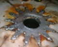
hey guys! so i have a 1990 maxima basically stock but i have no acc power so when i turn the key to on im just wasting my time. what happened was on the positive battery terminal theres was a little wire (from 2 to 3 in the picture) that completly melted off so all thats plugged in is the clips so im guessing something shorted out but how do i go about fixing that?? any ideas would be great! thanks in advance
http://carphotos.cardomain.com...e.jpg
Help!: No power!
-
hollabakzach23
- Posts: 18
- Joined: Sat Jun 06, 2009 8:50 am
- Car: 1993 nissan 240sx hatch, 1993 240sx coupe, 1998 altima, and the newest addition the 1990 maxima!!
-
MinisterofDOOM

- Moderator
- Posts: 30928
- Joined: Wed May 19, 2004 5:51 pm
- Car: 1962 Corvair Monza
1961 Corvair Lakewood
1974 Unimog 404
1997 Pathfinder XE
2005 Lincoln LS8
Former:
1995 Q45t
1993 Maxima GXE
1995 Ranger XL 2.3
1984 Coupe DeVille - Location: The middle of nowhere.
Re: Help!: No power! (hollabakzach23)
I'd replace the positive battery cable. Had to do that on mine a couple years ago. It's not a bad job.
-
hollabakzach23
- Posts: 18
- Joined: Sat Jun 06, 2009 8:50 am
- Car: 1993 nissan 240sx hatch, 1993 240sx coupe, 1998 altima, and the newest addition the 1990 maxima!!
Re: Help!: No power! (hollabakzach23)
alright what all needs to be done to do that because its all one harness so arent i gunna have to cut wires or how would i go about doin that??
-
hollabakzach23
- Posts: 18
- Joined: Sat Jun 06, 2009 8:50 am
- Car: 1993 nissan 240sx hatch, 1993 240sx coupe, 1998 altima, and the newest addition the 1990 maxima!!
Re: Help!: No power! (hollabakzach23)
also would that be a reason for it to kill the battery bc i bought a new battery last month and i had to get it fully charged and it like kills the battery every two or three days
-
loystock
- Moderator
- Posts: 2072
- Joined: Sun Sep 21, 2003 9:12 pm
- Car: 10 Honda Pilot
97 Infiniti Q45
03 Infiniti Q45
97 Infiniti I30
06 Infiniti M35 Sports
04 G35 & 99 I30-RIP - Location: San Jose, CA
Re: Help!: No power! (hollabakzach23)
You have a short circuit somewhere. Verify all leads from the battery positive side are disconnected and use an ohmmeter to measure resistance w.r.t. Ground to locate the short circuit. If not, use an ammeter (highest range possible) and connect in SERIES between the batt. Positive side and the lead on each harness.
-
hollabakzach23
- Posts: 18
- Joined: Sat Jun 06, 2009 8:50 am
- Car: 1993 nissan 240sx hatch, 1993 240sx coupe, 1998 altima, and the newest addition the 1990 maxima!!
Re: Help!: No power! (loystock)
alright so unplug the clips from the battery terminal and test them with an ohmmeter and ground it to the battery? what should they read?? also im not sure i understand the last part of your post?? i figured i had a short but where is a general location of where it may be comming from? thanks for the help btw!loystock wrote:You have a short circuit somewhere. Verify all leads from the battery positive side are disconnected and use an ohmmeter to measure resistance w.r.t. Ground to locate the short circuit. If not, use an ammeter (highest range possible) and connect in SERIES between the batt. Positive side and the lead on each harness.
-
loystock
- Moderator
- Posts: 2072
- Joined: Sun Sep 21, 2003 9:12 pm
- Car: 10 Honda Pilot
97 Infiniti Q45
03 Infiniti Q45
97 Infiniti I30
06 Infiniti M35 Sports
04 G35 & 99 I30-RIP - Location: San Jose, CA
Re: Help!: No power! (hollabakzach23)
Isolating the cause of a battery drain requires basic knowledge of electrical system and related test meters. A car battery has two connectors – negative lead goes to the car body/chassis/engine (Ground) while the positive goes to a Distribution/Fuse Box where the power is distributed to the major loads – starting system, charging system, ignition, engine control, lights, cooling fans, accessories, etc., via hard-wire, fusible link, fuse, CB, relay or combination thereof, depending on the application. In some cases, the positive side, in addition to the main connector, may have one or more additional leads connected to it which may have their own fusible link.
In a typical car electrical system, there is always a parasitic drain even if the engine is not running, i.e., something will draw current from the battery, like the ECM, security system, etc. So a system may have a parasitic drain of 0.05 Amps (50mAmps) or less. Anything more than that indicates an abnormal load, indicative of a short circuit. Hence if the car will not be used for an extended period of time, it would be better to disconnect the battery (negative side preferred) to prevent it from being discharged. When you do this, you may have to re-adjust the clock, re-tune you favorite radio stations, etc. when you reconnect the battery.
You have to isolate the source of your battery drain problem. To do so, disconnect all connectors from the positive side of the battery but keep the negative side intact. Start with the main leads that were disconnected from the positive side of the battery and check each one w.r.t. Ground(engine or chassis). The resistance measurement with an ohmmeter should normally indicate OPEN circuit (infinity) to as low as 250 ohms (assuming a parasitic drain of @ 0.05Amp). A reading close to ZERO indicates a short circuit. If the main leads tested OK, then you have to go to the FUSIBLE LINKS (large metal fuses for heavy loads) side of the power distribution and test each one for short circuit. The fusible link has to be pulled out to test the circuit downstream. Once a short circuit is identified, further isolation can be done by pulling the smaller fuses one at a time to narrow down the problem component.
There are times that a short circuit will only show up in a ‘live’ circuit. In that case, you need an AMMETER which must be connected in SERIES (positive lead of the ammeter to the positive side of the battery and the negative lead to the circuit under test). Since you don’t know the level of current that may flow, it would be better to always start at the highest current range in the ammeter then gradually decrease it. Furthermore, a circuit may require the IGNITION to be ON to provide power to that circuit.
It would help you a lot if you can download a copy of the Electrical Wiring Diagrams available from the FSM (Factory Service Manual).
Modified by loystock at 6:21 PM 8/19/2009
-
hollabakzach23
- Posts: 18
- Joined: Sat Jun 06, 2009 8:50 am
- Car: 1993 nissan 240sx hatch, 1993 240sx coupe, 1998 altima, and the newest addition the 1990 maxima!!
Re: Help!: No power! (loystock)
alright thanks for that its pretty clear now! i got another one for you now do you think it could have anything to do with just an unsolid grond from the battery because there was one of those rubber covers that go over ground wires for an amp and it was completly melted to it i just undid the ground from the block and peeled it off with pliers and cleaned it with a wire brush so maybe ill try and replace the link that melted and go from there?! but i will definatley go ahead and get the readings and figure out what to do next thanks for the quick reply!
-
hollabakzach23
- Posts: 18
- Joined: Sat Jun 06, 2009 8:50 am
- Car: 1993 nissan 240sx hatch, 1993 240sx coupe, 1998 altima, and the newest addition the 1990 maxima!!
Re: Help!: No power! (hollabakzach23)
hey guys i fixed it!!! so heres what i did i took off the whole ground cable and there was a melted rubber sleeve on it that goes on like power wire for an amplifier. so i peeled it off and ripped the wire out of the clips from 2 to 3 in the picture above and i crimped some primary wire on to those little tabs that you put on aftermarket speakers and slid them onto the clips, plugged them into the battery terminal and re grounded the battery started the car and it started without hesitation! the wire didnt melt down or anything so im hoping were good to go!!!
-
loystock
- Moderator
- Posts: 2072
- Joined: Sun Sep 21, 2003 9:12 pm
- Car: 10 Honda Pilot
97 Infiniti Q45
03 Infiniti Q45
97 Infiniti I30
06 Infiniti M35 Sports
04 G35 & 99 I30-RIP - Location: San Jose, CA
Re: Help!: No power! (hollabakzach23)
Excellent! Just make sure the battery ground wire is well insulated to prevent short circuit in the future. The same applies to the positive leads.
-
hollabakzach23
- Posts: 18
- Joined: Sat Jun 06, 2009 8:50 am
- Car: 1993 nissan 240sx hatch, 1993 240sx coupe, 1998 altima, and the newest addition the 1990 maxima!!
Re: Help!: No power! (loystock)
oh yeah for sure i may just go ahead and buy new power/ground wires this weeekend i know the "if it aint broke dont fix it" saying but its not expensive and a little precautionary i think. i would like to thank you for all the great advice by the way! do you have any idea where i can find a fairly inexpensive cat back for my 3rd gen because thats the next issue i need to fix i have a leak comming from the cat im almost positive and the owner before me just patched it up but i want to replace the whole system anyways
-
loystock
- Moderator
- Posts: 2072
- Joined: Sun Sep 21, 2003 9:12 pm
- Car: 10 Honda Pilot
97 Infiniti Q45
03 Infiniti Q45
97 Infiniti I30
06 Infiniti M35 Sports
04 G35 & 99 I30-RIP - Location: San Jose, CA
Re: Help!: No power! (hollabakzach23)
I don't believe in that adage "if it ain't broke don't fix it." Having worked in the airline industry for 18 years and then semiconductor for 13 years, preventive maintenance is the way to go...and that also applies to all the cars that I've owned.
For OEM parts, IoS a.k.a. everythingnissan.com is the best place to go at 25% off MSRP. But an OEM cat will cost you @ $1000. The catalytic converter contains precious metals like palladium, rhodium, platinum, etc. needed to oxidize/reduce the toxic gases (NOx, CO and HC) from the exhaust, hence the high cost. For the age of your car, no offense meant, I suggest getting an OEM-compatible cat (@ $100 on-line) instead of an OEM. These non-OEM cats have less precious metals inside the honeycomb and will probably last 1-3 years.
For OEM parts, IoS a.k.a. everythingnissan.com is the best place to go at 25% off MSRP. But an OEM cat will cost you @ $1000. The catalytic converter contains precious metals like palladium, rhodium, platinum, etc. needed to oxidize/reduce the toxic gases (NOx, CO and HC) from the exhaust, hence the high cost. For the age of your car, no offense meant, I suggest getting an OEM-compatible cat (@ $100 on-line) instead of an OEM. These non-OEM cats have less precious metals inside the honeycomb and will probably last 1-3 years.
-
hollabakzach23
- Posts: 18
- Joined: Sat Jun 06, 2009 8:50 am
- Car: 1993 nissan 240sx hatch, 1993 240sx coupe, 1998 altima, and the newest addition the 1990 maxima!!
Re: Help!: No power! (loystock)
okay okay i definatley like the way you think!!
yeah i looked on courtesy and i wanted like an aftermarket exhaust possibly buuut for now i have yet another problem my check engine light came on today and its driving reeaaal rough when its at idle it jumps up and down and i have to give it a lot of gas and it slowly revs up and eventually like "catches" i guess you could say and starts driving normally?? any ideas on that?
yeah i looked on courtesy and i wanted like an aftermarket exhaust possibly buuut for now i have yet another problem my check engine light came on today and its driving reeaaal rough when its at idle it jumps up and down and i have to give it a lot of gas and it slowly revs up and eventually like "catches" i guess you could say and starts driving normally?? any ideas on that?
-
loystock
- Moderator
- Posts: 2072
- Joined: Sun Sep 21, 2003 9:12 pm
- Car: 10 Honda Pilot
97 Infiniti Q45
03 Infiniti Q45
97 Infiniti I30
06 Infiniti M35 Sports
04 G35 & 99 I30-RIP - Location: San Jose, CA
Re: Help!: No power! (hollabakzach23)
Without knowing what triggered the CEL, it would be difficult to troubleshoot. Besides, I'm not familiar with the earlier models of Maxima. So I'm just using my knowledge of the I30/4th Gen Maxima and make some assumptions. It could be the IACV (Idle Air Control Valve), a fried ECU (Engine Control Unit), a MAF (Mass Air Flow() sensor or fuel system problem (Fuel Filter or Fuel Pump). An unstable idle is usually attributed to IACV. An EGR (Exhaust Gas Recirculation) can also result in erratic engine behavior.
It would be better to take you car to AutoZone for free diagnostics. I think some AAMCO shops offer free diagnostics too. A car shop may charge you $25-50 for diagnostics. Please note that your car is pre-OBD II and may required a different data link connector and protocol.
It would be better to take you car to AutoZone for free diagnostics. I think some AAMCO shops offer free diagnostics too. A car shop may charge you $25-50 for diagnostics. Please note that your car is pre-OBD II and may required a different data link connector and protocol.
-
hollabakzach23
- Posts: 18
- Joined: Sat Jun 06, 2009 8:50 am
- Car: 1993 nissan 240sx hatch, 1993 240sx coupe, 1998 altima, and the newest addition the 1990 maxima!!
Re: Help!: No power! (loystock)
yeah well when i checked the codes it gave me 33 which if i remember correctly is the heated o2 sensor so im probably going to tackle that today and probably replace the fuel filter at least what do i need to do to adjust the IACV?
-
loystock
- Moderator
- Posts: 2072
- Joined: Sun Sep 21, 2003 9:12 pm
- Car: 10 Honda Pilot
97 Infiniti Q45
03 Infiniti Q45
97 Infiniti I30
06 Infiniti M35 Sports
04 G35 & 99 I30-RIP - Location: San Jose, CA
Re: Help!: No power! (hollabakzach23)
Your Maxima belongs to the 1989-1994 generation. Below is the link to 1994 Maxima FSM. I hope it applies to your car.
[http://www.nicoclub.com/FSM/maxima/1994/][/URL]
[http://www.nicoclub.com/FSM/maxima/1994/][/URL]