This is BS to me, especially the one I see here. So someone clear this up with science and not superfluous "feels" statements please...even better documented evidence.
I've gone all over the grounding kit I see on this forum as well as other sites and searches. All of them seems to be a bunch of excessive, unnecessary, over indulgent wiring.
You can't get a flood through a straw, so why is everyone taking 16-14gauge wire and piping that to 4-0gauge wire all over the engine to a grounding point and saying its doing something.
The general theoretical principle of this is to provide a bigger gauge wire for a better return path, thus producing better cleaner electricity, and slightly higher voltage. However, the bigger gauge wire is always picking up from a smaller wire in these kits. A 14-16gauge wire going to a 4gauge to a grounding point. And also one grounding point to another. This doesn't make sense. If this was really suppose to do something, the 4gauge would HAVE to be coming directly from the source and not have an intimidiary wire in between. That to me defeats the purpose. Think about it, electricity is like water, if you take a 2" diameter pipe and feed that into a 15" diameter pipe, it doesn't change the amount or force of water coming out the 15" as was coming out the 2". And even reverse that and pour the 15" into the 2"; it would burn up the 2" because too much was being poured it. So why? How exactly does this grounding kit the way it is help?
I believe there is potential, however I'm not all the way sold, and definitely not the way this particular kit is designed and many others i see floating around. If I were to rewire the electrical system for better power all I would do is 3-5 wires.
1/ change the positive wire alternator to battery
2/ negative battery to chassis
3/ chassis to engine block
4/ the ecu if I have direct access
4gauge standard, and 0-4gauge with aftermarket toys installed.
All other points I don't see a point to. And thus this can def be done way cheaper than this kit is being sold for(easily 50%)...if this stuff actually makes a significant difference.
So who can REALLY explain this to me
Grounding kit myth
-
Larz
- Moderator
- Posts: 2894
- Joined: Thu Feb 21, 2013 8:55 pm
- Car: 2019 Q70-L RWD
- Location: Ft Lauderdale, Florida
- Contact:
Re: Grounding kit myth
I could not agree more, TDot. If a gounding kit was needed, the car would come with it. It's a project that has no testing to back it up and no recorded improvement beyond the claims of those who sell them. As you say, common sense confirms it can't do anything that is worth the trouble or expense of adding it.
This reminds me of the peeps who install "COLD" air intakes (CAI's). Extensive testing has been done on them and prove beyond doubt that if you're really lucky you may get 1% increase in HP and absolutely NONE of them actually provide cold air - usually the same air temp as the factory set up. They make the engine appear more powerful, and make a nice sound, but are a waste of money based on actual testing on a Dyno.
Then there is the magnet attacment that peeps put on their fuel line. Fuel is NOT magnetic and is not affected in the least by this contraption.
Keep the engine bay clean, keep clean air filters, use the proper octane rated fuel, and change the PCV valve, MAF, and O2 sensors when needed. Change the oil and filter at proper frequency. That ensures you're getting the most out of the engine.
-
EniGmA1987
- Posts: 2258
- Joined: Tue Apr 28, 2009 5:13 am
- Car: '06 Infiniti M35 Sport
Re: Grounding kit myth
I dont know what you are seeing with grounding kits and their claims and all that but let me explain how the kit works:
most things in the engine bay are grounded, however they ground to the chassis usually. This in turns eventually gets to a point where the car picks it up and sends it to the negative battery terminal as a "ground".
A ground in a circuit does not mean an earth ground, it is simply the point of a circuit design that is specified as ground and can be lots of things really. Normally in a circuit such as a machine the ground really is an earth ground, but in a lot of computer electronics ground is considered a 0V side of a DC supply or even *can* have things come back to a -12v area to be called out as ground in the design.
The grounding kit takes things that need good grounding, such as the TCU and ECU, and throttle body and provides a new, dedicated path from that directly (or almost directly) to the negative battery terminal. Good kits use 4 AWG wire, cheaper kits go up to smaller gauges. Even 10 AWG dedicated ground might be better than some of the grounds though, but I dont remember seeing any that small.
This kit I have has a couple different places all meet at a spot on the lower plenum (which is basically the engine block), and then goes from there into the battery compartment. There are only like 6 or maybe 7 wires total, and it uses 4AWG wire (I just looked it up). So yes there may be some 0-4AWG wire in the engine bay, but it isnt really being used as an effective ground in most circumstances. The grounding kits take devices that need a solid connection and dont have one, and provides that connection.
The reason these things arent done on all cars from the factory is that grounding to the chassis as a pathway back is technically "good enough" and it also saves on cost (copper is expensive) and time of installing these wires. The factory can save millions od Dollars by just grounding to the chassis instead of providing dedicated grounds. Also, if you make the kit yourself it only costs like $30-40. Just find a place that sells good automotive wire and buy a 25' cut and some (solid copper, heavy duty) crimp connectors. The kits are overpriced because the person has already done the measuring work, that is it really.
As for measured improvements, it is hard to provide because average joe doesn't have the equipment to measure circuit speed. I did see a small improvement in voltage levels though, which is an actual measurement and can be seen. I suppose someone could measure response times of various things, but that might be hard to do as well since I dont think our OBDII port and ECU is set up for that type of diagnostic. I can say I did notice improvements in shift response when in manual mode and driving hard. Audio also got louder by about 1 bar on the volume indicator too. Supposedly the grounding kits can help throttle response a bit too, not sure if I noticed much of a difference or not. It would only help in electronic throttle control systems like we have anyway, not the mechanical throttle control systems.
This is where things come back to on the engine in my kit:
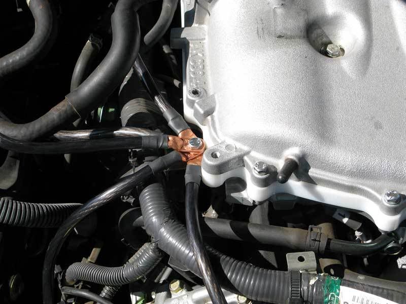
and the throttle body ground:

most things in the engine bay are grounded, however they ground to the chassis usually. This in turns eventually gets to a point where the car picks it up and sends it to the negative battery terminal as a "ground".
A ground in a circuit does not mean an earth ground, it is simply the point of a circuit design that is specified as ground and can be lots of things really. Normally in a circuit such as a machine the ground really is an earth ground, but in a lot of computer electronics ground is considered a 0V side of a DC supply or even *can* have things come back to a -12v area to be called out as ground in the design.
The grounding kit takes things that need good grounding, such as the TCU and ECU, and throttle body and provides a new, dedicated path from that directly (or almost directly) to the negative battery terminal. Good kits use 4 AWG wire, cheaper kits go up to smaller gauges. Even 10 AWG dedicated ground might be better than some of the grounds though, but I dont remember seeing any that small.
This kit I have has a couple different places all meet at a spot on the lower plenum (which is basically the engine block), and then goes from there into the battery compartment. There are only like 6 or maybe 7 wires total, and it uses 4AWG wire (I just looked it up). So yes there may be some 0-4AWG wire in the engine bay, but it isnt really being used as an effective ground in most circumstances. The grounding kits take devices that need a solid connection and dont have one, and provides that connection.
The reason these things arent done on all cars from the factory is that grounding to the chassis as a pathway back is technically "good enough" and it also saves on cost (copper is expensive) and time of installing these wires. The factory can save millions od Dollars by just grounding to the chassis instead of providing dedicated grounds. Also, if you make the kit yourself it only costs like $30-40. Just find a place that sells good automotive wire and buy a 25' cut and some (solid copper, heavy duty) crimp connectors. The kits are overpriced because the person has already done the measuring work, that is it really.
As for measured improvements, it is hard to provide because average joe doesn't have the equipment to measure circuit speed. I did see a small improvement in voltage levels though, which is an actual measurement and can be seen. I suppose someone could measure response times of various things, but that might be hard to do as well since I dont think our OBDII port and ECU is set up for that type of diagnostic. I can say I did notice improvements in shift response when in manual mode and driving hard. Audio also got louder by about 1 bar on the volume indicator too. Supposedly the grounding kits can help throttle response a bit too, not sure if I noticed much of a difference or not. It would only help in electronic throttle control systems like we have anyway, not the mechanical throttle control systems.
This is where things come back to on the engine in my kit:
and the throttle body ground:
-
Ilya

- Moderator
- Posts: 9205
- Joined: Fri Apr 23, 2010 11:20 pm
- Car: 2011 M56x but I spend a lot of time on my 2015 Kawasaki Vulcan S. Former owner of a 2007 M35x. Also take care of my wife's 2016 QX60.
- Location: Charlotte, NC
- Contact:
Re: Grounding kit myth
While a grounding kit isn't need, cleaning existing grounds from oxidation, etc. IS beneficial. Especially for electronics (such as sound systems). Because it helps electronics, this CAN make your car shift better, etc. but it's likely very small and you would have to be EXTREMELY in-tune with the characteristics of you car to tell.
I know on my Maxima, when I cleaned all my grounds, my subs hit WAAYYY harder because my head unit was putting out the beats much better since the stock electrical harness for the stereo was now grounded better.
I wouldn't pay $100 for a grounding kit, but I certainly would take an hour or two and really clean all of the grounds that I can get to.
-
svard75

- Posts: 1564
- Joined: Mon May 11, 2009 3:26 am
- Car: 06 M35x
- Location: Toronto, Ontario, Canada
Re: Grounding kit myth
A grounding kit could be beneficial in the following circumstances:
Cleaner power for the spark plugs
Cleaner power for the sensors
With age metal to metal contacts corrode and corrosion acts more like resistance. Think about all the sensor locations and the sections. For example the transmission has numerous sensors and solenoids. The transmission is connected to the main block. The contact between the two sections may not be as good as brand new.
Some grounding kit authors argue that the return path to the battery is shorter by implementing a grounding kit, however think about how quickly electricity flows. Will it really make that much difference? Perhaps in older cars.
-
EniGmA1987
- Posts: 2258
- Joined: Tue Apr 28, 2009 5:13 am
- Car: '06 Infiniti M35 Sport
Re: Grounding kit myth
Also remember though that flowing through the chassis to get back to ground means it travels through steel, which has 4-5x the resistance of copper. The pathway is also longer so not only will it take a tiny little bit more time, but you have more voltage drop by using the chassis to move electricity around instead of a dedicated ground pathway. I feel like this is where the benefits come from, the higher voltage. More voltage in audio usually means more volume (99% of the time volume is controlled by reducing the voltage through adding resistance to the audio signal), more voltage in lights means brighter output, more voltage to microcontrollers like the TCU and ECU shouldn't mean any better performance since it goes through its own regulation down and all that, yet somehow does seem to help shifting response so whatever but we get an improvement there. Do I think everyone should pay $100+ for a grounding kit? No of course not. But if you have the knowhow to do it for $50 or less than it would be worth doing. I also believe there are real, measurable improvements and have seen the difference first hand. It is a small difference, not some night and day obvious thing, but the difference is there.msvara wrote:Some grounding kit authors argue that the return path to the battery is shorter by implementing a grounding kit, however think about how quickly electricity flows. Will it really make that much difference? Perhaps in older cars.
-
svard75
- Posts: 1564
- Joined: Mon May 11, 2009 3:26 am
- Car: 06 M35x
- Location: Toronto, Ontario, Canada
Re: Grounding kit myth
What mount points did you use for each ground wire?
-
EniGmA1987
- Posts: 2258
- Joined: Tue Apr 28, 2009 5:13 am
- Car: '06 Infiniti M35 Sport
Re: Grounding kit myth
ECU, TCU, throttle body, engine block, negative battery terminal. Maybe another one or two IDK. This was so many years ago now that the kit was put in, either 2010 or 2011.
Re: Grounding kit myth
Another butt-dyno experience...I had a 97 I30t and added a heavier negative connection to the body and freshened up all ground connections that I could find.
The transmission response afterwards was impressive. Shifting was more firm, took less time and throttle response and idle were smoother, no question. There may have been a slight uptick in MPG but I did not do any before/after comparison.
That was all done at 135K miles.
The transmission response afterwards was impressive. Shifting was more firm, took less time and throttle response and idle were smoother, no question. There may have been a slight uptick in MPG but I did not do any before/after comparison.
That was all done at 135K miles.
-
svard75
- Posts: 1564
- Joined: Mon May 11, 2009 3:26 am
- Car: 06 M35x
- Location: Toronto, Ontario, Canada
Re: Grounding kit myth
Nothing wrong with that! I'll bet the freshening up of the existing connections made most of the difference.Double E wrote:Another butt-dyno experience...I had a 97 I30t and added a heavier negative connection to the body and freshened up all ground connections that I could find.
The transmission response afterwards was impressive. Shifting was more firm, took less time and throttle response and idle were smoother, no question. There may have been a slight uptick in MPG but I did not do any before/after comparison.
That was all done at 135K miles.
-
finikM35

- Posts: 248
- Joined: Thu Dec 20, 2012 8:36 pm
- Car: 2007 M35x tech package
5/16 plenum spacer, element 114 exhaust, ztube,k&n, grounding kit, uprev tuned, D2 coilovers. - Location: Brooklyn NY
Re: Grounding kit myth
Shifting is faster in manual mode idk how but it works. Haven't noticed anything else
Re: Grounding kit myth
Here's my issue, the engine block, off the top, is a bad idea to include in the scheme of a grounding block source, or meeting point. The reason for that is the heat and vibration introduce increased resistance and breakdown which can lead to lower voltage among other things. It's also a compromise midpoint if the battery is an absolute ground. All those rings bolted together on the engine is begging to come lose over time, granted since its all a "secondary grounding scheme" it won't actually cause a significant problem, but it will essentially be a bunch of useless wires in the car. Not to mention the potential for contamination and corrosion around and between the rings. If I were to do that...and I wouldn't...I would crimp all the wires together in a block (like some of the factory grounding). But I know that isn't really an option for the average due to the tool required. Also consider the multiple different metals in that chain (ring - copper wire - ring - alloy - ring - copper wire - ring - ground) which is also adding to the resistance and negating...what I'm assuming is oxygen free copper 4 gauge wire...the benefit of the resistance of the wire.
Getting the headlights brighter, windows winding faster, among other things, All you literally have to do is 1/ as IlyaKol said, clean the contacts (maybe sand things down a bit) or 2/ (preferred for guarantee) upgrade the battery+ to alternator, and battery- to chassis. That is literally it to get those exact results....$10.00-$20.00 and 20min. And for extra battery- to engine block and maybe add or upgrade the grounding straps. That's it, engine cleaner and less hocus pocus lol.
Also, distance in dc grounding through the chassis is nearly negligible since the car is solidly built with steel, not even worth considering in the grand scheme of things beyond safety.
My water and pipe analogy before may have been overstating it a bit, because increasing the wire does decrease the resistance, however, you don't put a city water main under your sink to wash dishes, thus you don't put a 4gauge to ground headlights back to the battery when the headlights are only pulling enough amps to require a 14gauge on the positive side. But I guess you can't go wrong with going bigger regardless, but my feeling its just a matter of where and how its implemented. And this to me is overkill and a bunch of redundancies that can POTENTIALLY (because I know you're going to say it never happened to you) cause more problems than it solves, and cost WAY more than is necessary. Like Larz said about the CAI, it all seems like a money scheme that suckers unsuspecting people in that don't have a full grasp on things...no offense to anyone because I am no expert.
All in all, if it works for you then great. But In the end I simply suggest people either do like IlyaKol suggests and clean, or me and limit, and I GUARANTEE you'll get the exact same results and better at 20-50% the cost depending on the gauge of wire, and WAY less time out your day.
The only thing I can't speak of is the shifting thing
-
EniGmA1987
- Posts: 2258
- Joined: Tue Apr 28, 2009 5:13 am
- Car: '06 Infiniti M35 Sport
Re: Grounding kit myth
What is "Ring" supposed to be in your example of how all the things become wired?
Re: Grounding kit myth
The ring is just the connector, which I'm sure is not oxygen free copper, slightly doubting it is even copper, and unsure of the type of metal all together. Nothing significant in it of itself, but matters in the grand scheme of the purpose of this and the amount of times it happens.
But again, if it is helping as it all is, then cool. Just something to think about for the next set of people going this direction.
But again, if it is helping as it all is, then cool. Just something to think about for the next set of people going this direction.
-
EniGmA1987
- Posts: 2258
- Joined: Tue Apr 28, 2009 5:13 am
- Car: '06 Infiniti M35 Sport
Re: Grounding kit myth
That is what I assumed you meant by ring but just wanted to be sure. The ring or lug should always be solid copper in these sorts of applications, which is the same as the wire. Even if the lug is not OFC, the different is only 1% in conductivity and is still FAR lower in resistance than steel. A lot of the things I am seeing you say here leads me to believe you dont have an electrician type of background, is that true?
Re: Grounding kit myth
Why? Because I say things like this?EniGmA1987 wrote:A lot of the things I am seeing you say here leads me to believe you dont have an electrician type of background
Have you looked at the voltage running through your car? I have? I'm getting 13.2V to my equipment at idle the last time I checked. That tells me my resistance is negligible in the grand scheme of things. Grounds...whenever possible...should never be daisy chained, whether nickel plated steel, plain steel, brass, copper, or any other type of interconnects. Direct is always best, or a centralized block. You might know for sure your eyelets are copper, and that is what should be used, but not everyone knows that, and not all eyelets are sold as that. Does the steel chassis have more resistance than the copper eyelets? Yes. But I'd rather deal with the resistance I've known and had no issue with than potentially introduce more resistance through daisy chained connections, and ground potential issues from the multiple connections, especially if I have aftermarket toys.TDot wrote:Also, distance in dc grounding through the chassis is nearly negligible since the car is solidly built with steel, not even worth considering in the grand scheme of things beyond safety.
No I don't have an electrician background...as far as formal education, journeyman, ibew, or anything. However, experience in rewiring houses, building studios from ground up with common grounds and direct auto switch backup generators, general electrical tinkering, my job as a telecom engineer, and speaking to people with degrees in this gives me the basic knowledge to know that this is an over complicated, unnecessary, redundant mess. It doesn't take an electrical background to know that THIS shouldn't be done and is not going to help beyond what I've previously stated.
I do have enough electrical background to know you don't mount a grounding interconnect on a heat producing point which will increase the resistance throughout all the grounds and therefore potentially nullify what you are trying to do depending on your wire gauge and making things worse. Enough to know not to pile grounding points on top of each other on a vibrating surface instead of using a good conductive block or clamp somewhere that's not prone to excessive vibration. Enough to know not to make unnecessary interconnects where I'd be loosing a small amount of voltage and changing the ground potential which will cause a ground loop. Enough to know the "slight" resistance I already have through the chassis is better than changing the ground potential. Enough to know if I'm going to go out my way to achieve something specific I'm going to do it right and the best way possible. No formal education on this, and I don't know everything, but more than enough knowledge to question this setup. IF I was to go this route with all of these unnecessary wires, this is what I'd do:

Or
NOT THIS:

And if I HAD to pile a bunch of wires on each other, This is the proper way:

But what do I know. Anyway, I'm done with this, I got my answer. Everyone is free to do what they want with their car.
-
svard75
- Posts: 1564
- Joined: Mon May 11, 2009 3:26 am
- Car: 06 M35x
- Location: Toronto, Ontario, Canada
Re: Grounding kit myth
Maybe I missed an earlier comment but did any of you guys ground directly to the transmission body? I remember this being a huge advantage on my Acura cl-s.
Once the car is running you would want the ground running directly to the alternator not the battery for a cleaner more direct approach. The charging system diagram indicates that once the engine is on power is fed to the entire network via the alternator. So those images of wires leading back to the battery is for show more than function. Okay they may have slight function because the alternator is also charging the battery but if that wire is not upgraded then you have a bottleneck.
Once the car is running you would want the ground running directly to the alternator not the battery for a cleaner more direct approach. The charging system diagram indicates that once the engine is on power is fed to the entire network via the alternator. So those images of wires leading back to the battery is for show more than function. Okay they may have slight function because the alternator is also charging the battery but if that wire is not upgraded then you have a bottleneck.
Re: Grounding kit myth
TDot I think you should do a test on your car to see if you feel a diff.
You should start by cleaning your oem negative cable wire and drive for a week, tell us what you feel.
After 1 week install a 4g wire to the trans and let us know if your shifting gets any better as so many are stating. IMO testing is the only way to find PROS & CONS
My car is in the shop now but sometime in the near future I'll be cleaning the oem ground and adding 1 4g wire to the trans.
Hey I did a test on a new oem filter vs a K&N drop in filter, which is the reason I don't have a RC2 or any other CAI or after-market air system in my car. When I posted my findings most didn't believe, some did and reported the same as I did. So I try to not post about the subject anymore, I just go to the next thread but at the end I tested myself and saved $250

Re: Grounding kit myth
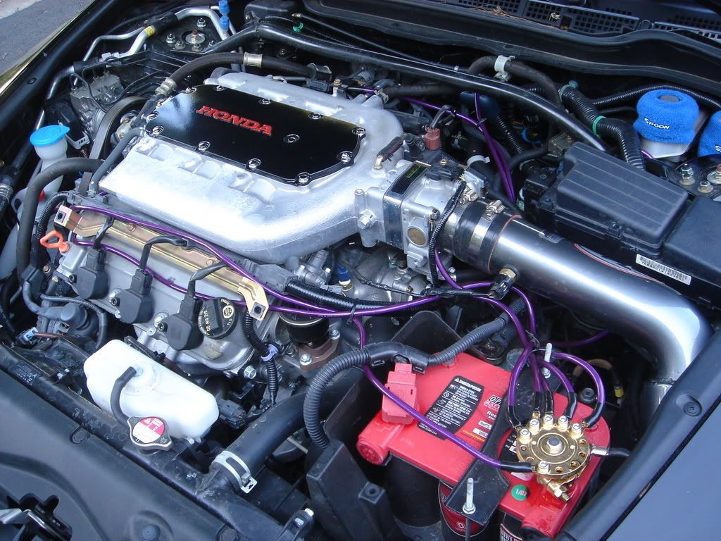
Some great information here. I like the design of the kits that are on the Hondas. Other than the Throttle body (pictured in a reply) and trans casing, can someone please point out, WITH a picture, the other recommended points? I would like to put together a video for this mod as I did for the headlight adjustment.
Thanks for any and all help.
Thanks for any and all help.
-
The00Dustin
- Posts: 1041
- Joined: Mon Jun 29, 2009 4:05 am
- Car: 2006 Infiniti M45
- Location: Bloomington, IN
Re: Grounding kit myth
I really didn't want to respond to this post, but I couldn't stand it. Introduce more resistance? Are we somehow removing the steel chassis from the loop? Like water, electricity follows the path of least resistance, so adding a new path cannot add additional resistance unless the old path is modified. Maybe resistance could be created if you are suggesting a screw that was touching the chassis isn't anymore [as much; the threads still are] and then corrosion forms between the screw and loops or the loops and chassis [and still not the threads and the chassis], but that only applies where there is only one grounding point on whatever is being grounded and no pre-existing grounding wire that can either remain directly touching the grounding point or at least directly touching the screw [can't think of a real example where it is forced to apply, actually]. Since you state that it is negligible either way, I feel like the adding more resistance comment was a little bit more over the top than the water pipe example (which was reasonable in my opinion). On that note, let me try to be constructive and state that I added a grounding kit without expectations of improvement and explain why.TDot wrote:But I'd rather deal with the resistance I've known and had no issue with than potentially introduce more resistance through daisy chained connections, and ground potential issues from the multiple connections, especially if I have aftermarket toys.
1) Cleaner electricity is always better. I'm in IT, and I've had to mess with all kinds of electronics, and I've seen all kinds of problems with less-than-adequate grounds (or other dirty electricity problems, some that I can't explain or get any meter to show). Never mind the shorter path, never mind that the kit pictured here isn't optimal (because it daisy chains or goes to the battery instead of the alternator), suggesting that these are problems ignores the fact that the steel body has plenty of welds in it, so it is also "daisy chained", more in some places than the grounding kit. Moreover, I haven't looked, so I could be wrong here, but I have always assumed that there is a good ground wire between the alternator and the battery, because the alternator needs a good connection to charge the battery. If I am correct, then grounding at the battery should be even more negligible vs grounding at the alternator than grounding at the chassis could vs a grounding kit.
2) Redundancy is always better. My previous car would have ABS quit randomly in wet weather, generally when I might need it most, cleaning grounds didn't fix it, but if it would have, then a redundant ground path might have prevented it, which would have been nice. More importantly, these cars are filled with electronics, my grounding kit also goes into the dash and grounds the ECU, I don't want my equipment failing, so if this could potentially prevent that, then it is worth more and costs less than a factory extended warranty.
That's all I've got, but for no more than it costs to buy a kit or do it yourself, that seems like enough to me. Also, for the record, I've got the M45, and my kit doesn't link all the wires together on the engine. Moreover, I did notice slightly smoother shifting and acceleration, nothing dramatic, the TSB for hard shifting and the recall for the accelerator made much more dramatic differences than the grounding kit, but it was there, so perhaps a better ground can also better regulate a manufacturer defect or two whether you know about them or not.
EDIT: Added comments in []'s to make sure it was obvious that I wasn't really giving much, if any, on the "introduce more resistance" argument.
-
EniGmA1987
- Posts: 2258
- Joined: Tue Apr 28, 2009 5:13 am
- Car: '06 Infiniti M35 Sport
Re: Grounding kit myth
I was just wondering because some of the things you say don't make a lot of sense to me from how electrical systems work. I am not sure if you are just looking at that picture you posted of a VQ with a grounding kit and are getting bad ideas about all kits, or if you are just not understanding how these kits are designed and installed. The first picture you just posted about how you would do it (this one:)TDot wrote:snip
is the same way the grounding kits for our car are designed, just not quite as fancy looking with a new dedicated grounding bar for things to meet at. Other than that it is pretty much the same... Also, I just measured my voltage today and I get 14.32v in my electrical system, so apparently that 4-5x increase in resistance that you are happy with actually does matter.
Re: Grounding kit myth
^^^has nothing to do with looking fancy, its simply done properly. A proper grounding block not mounted to a heat producing source, which has been ONE of my main arguments about the infiniti, or your, kit's specific setup. If you cant understand that from my explanation or see that in the example, i cant make it any clearer. I'm glad you got an improved voltage, I never said you wouldn't get more voltage (i'll admit I had doubts of how much), but I question if you'd get the same improvement with less wiring and better placement, which I believe you can; And if your implementation couldn't be better as for resistance and possible breakdown points. This is all about making it the best it can be regardless if its already doing what it should be and at what cost. Where are you taking that measurement and how long was the engine running before you took it? Is that idle or revving? If that's idle, isn't it too much because running you would be approaching 15v? I ask because I've been told voltage that high in the car is bad, correct me if I'm wrong. If I remember correctly I'm at 13.9-14.2v running, and this is at a ground block distro in my trunk grounded to the back seat.
Dustin, my argument against the daisy chain is not based on the the rest of the grounding being taken out of the equation, or resistance being added in the entire grounding system (which you are wrong on that statement that its not possible without changing the physical state of the existing ground by the way, but I'll say its unlikely in the confines of these grounding scenarios). My argument is strictly it is not the best way, and will get increased/more resistance...in the chain...VS a direct run and potentially vs the chassis, and have more breakdown points. Nothing more nothing less.
Everything you stated on why the daisy chain would fail in it of itself as a grounding scheme is my point. So what's your point? I understand, you just wanted to join the conversation lol. Is my phrasing over the top? Maybe, but my point is, IF the resistance is increased IN THESE DAISY CHAINED CONNECTIONS, then its useless to me because I'm not concerned about redundancy and marginal improvements that can't easily be recognized, I'm concerned about the best path potential and obvious tangible benefits. Also, to compare the welds and joins of this chassis, which I believe is pretty solid and not spot, to the links in this chain that can vibrate loose and/or become corroded doesn't make too much sense and is over the top, so I'm not even going to touch that.
Like i said, this thing (improving the grounding) actually has me intrigued to do but in a more sensible way because ALL of these kits seem to be overindulgent wiring and not properly thought out to achieve the benefits that are sought after in the best way. And I'm sure redundancy, as much as it may be beneficial, is not the general purpose of these kits...and not what I'm looking for. So over the weekend I actually showed this to a few people who have a couple decades of experience with electricity over me (electrical engineering degrees, electrical utility engineer, someone i simply know has more knowledge than me on this stuff, and a general electrician 15 years in), they all said its a hot mess fast and furious crap...well only one said the fast and furious crap.
Consensus:
beneficial--in principle yes.
specifics of improvement--faster window, faster starter, brighter lights, less dimming, any more is unknown and not worth depending on.
worth the cost--no($100+)...and they are not talking about people who need redundancy because their ground or electrical system is poor.
a better way to do it--most definitely.
None of them are hard car people, two car tinkerers, so they couldn't co-sign the throttle stuff, one said def not, another said he can't see it, the other two said they just didn't know. But that isn't a sticking point with me either way.
This is an example of why I say all these kits with all of these wires are unnecessary...besides the whole redundancy argument.

That's all that's needed as far as I see, minus that fuse on the alternator. And maybe a ground from the alternator to the chassis or battery? I haven't tried either but I will bet this will give the same results or better, and its neater and less convoluted. And this whole argument on the ecu ground, has anyone lost their computer to a bad ground yet in these cars(I'm actually asking, not not being facetious)? Anyone who has had their ecu replaced, was your ground replaced? The statement of just in case with no prior evidence is just not good enough for me. There's nothing that proves this is necessary, and I can't disprove it, so it is what it is if you want to do it.
This whole discussion is getting overly complicated and redundant, especially arguing finite points and wording to prove points that probably won't be noticed (and I'll admit my fault in that). My initial issue was the benefits in the wiring implementation, and then became setup. The principle of better grounding and some of the benefits is sound and agreed on...no argument, IF its done right. So can we move on? I found two things called the big 3 and big 4 which is exactly and all I've been stating ^^the pic above^^. Read up on them. They are basically diy kits with more precision and logic in implementation and thus definite improvements instead of hijacking a bunch of grounding wires that don't need to be touched and running all over the engine...IMO.
I'd actually like to discuss the grounding of the alternator and how that can SPECIFICALLY be beneficial and an IMPROVEMENT, and how to go about it with respects to the grounding to the battery. Not just a matter of that's how it should be off of simple principle and theory. I thought since its attached to the engine block, grounding to it is a mute point.
Note, none of the capitalization is yelling, just emphasizing the points since they seem to be overlooked.
Dustin, my argument against the daisy chain is not based on the the rest of the grounding being taken out of the equation, or resistance being added in the entire grounding system (which you are wrong on that statement that its not possible without changing the physical state of the existing ground by the way, but I'll say its unlikely in the confines of these grounding scenarios). My argument is strictly it is not the best way, and will get increased/more resistance...in the chain...VS a direct run and potentially vs the chassis, and have more breakdown points. Nothing more nothing less.
if I was to believe that would happen in these grounding situations, why would I argue in favor of adding direct lines or a centralized ground block away from a heat source?The00Dustin wrote:so adding a new path cannot add additional resistance
Everything you stated on why the daisy chain would fail in it of itself as a grounding scheme is my point. So what's your point? I understand, you just wanted to join the conversation lol. Is my phrasing over the top? Maybe, but my point is, IF the resistance is increased IN THESE DAISY CHAINED CONNECTIONS, then its useless to me because I'm not concerned about redundancy and marginal improvements that can't easily be recognized, I'm concerned about the best path potential and obvious tangible benefits. Also, to compare the welds and joins of this chassis, which I believe is pretty solid and not spot, to the links in this chain that can vibrate loose and/or become corroded doesn't make too much sense and is over the top, so I'm not even going to touch that.
So why the hell you fighting me lol. And I'll take your co sign on the pipe analogy.The00Dustin wrote:my kit doesn't link all the wires together on the engine..
Like i said, this thing (improving the grounding) actually has me intrigued to do but in a more sensible way because ALL of these kits seem to be overindulgent wiring and not properly thought out to achieve the benefits that are sought after in the best way. And I'm sure redundancy, as much as it may be beneficial, is not the general purpose of these kits...and not what I'm looking for. So over the weekend I actually showed this to a few people who have a couple decades of experience with electricity over me (electrical engineering degrees, electrical utility engineer, someone i simply know has more knowledge than me on this stuff, and a general electrician 15 years in), they all said its a hot mess fast and furious crap...well only one said the fast and furious crap.
Consensus:
beneficial--in principle yes.
specifics of improvement--faster window, faster starter, brighter lights, less dimming, any more is unknown and not worth depending on.
worth the cost--no($100+)...and they are not talking about people who need redundancy because their ground or electrical system is poor.
a better way to do it--most definitely.
None of them are hard car people, two car tinkerers, so they couldn't co-sign the throttle stuff, one said def not, another said he can't see it, the other two said they just didn't know. But that isn't a sticking point with me either way.
This is an example of why I say all these kits with all of these wires are unnecessary...besides the whole redundancy argument.
That's all that's needed as far as I see, minus that fuse on the alternator. And maybe a ground from the alternator to the chassis or battery? I haven't tried either but I will bet this will give the same results or better, and its neater and less convoluted. And this whole argument on the ecu ground, has anyone lost their computer to a bad ground yet in these cars(I'm actually asking, not not being facetious)? Anyone who has had their ecu replaced, was your ground replaced? The statement of just in case with no prior evidence is just not good enough for me. There's nothing that proves this is necessary, and I can't disprove it, so it is what it is if you want to do it.
This whole discussion is getting overly complicated and redundant, especially arguing finite points and wording to prove points that probably won't be noticed (and I'll admit my fault in that). My initial issue was the benefits in the wiring implementation, and then became setup. The principle of better grounding and some of the benefits is sound and agreed on...no argument, IF its done right. So can we move on? I found two things called the big 3 and big 4 which is exactly and all I've been stating ^^the pic above^^. Read up on them. They are basically diy kits with more precision and logic in implementation and thus definite improvements instead of hijacking a bunch of grounding wires that don't need to be touched and running all over the engine...IMO.
I'd actually like to discuss the grounding of the alternator and how that can SPECIFICALLY be beneficial and an IMPROVEMENT, and how to go about it with respects to the grounding to the battery. Not just a matter of that's how it should be off of simple principle and theory. I thought since its attached to the engine block, grounding to it is a mute point.
Note, none of the capitalization is yelling, just emphasizing the points since they seem to be overlooked.
-
The00Dustin
- Posts: 1041
- Joined: Mon Jun 29, 2009 4:05 am
- Car: 2006 Infiniti M45
- Location: Bloomington, IN
Re: Grounding kit myth
Clearly I misunderstood you, so no arguments here. Regarding the ECU, you can consider that as paranoia in my case if you'd like. My thinking is I plan on driving a lot more miles than most people and don't want to replace it in the long run either, so for longevity in electronics, cleaner electricity is better. It honestly seems like I had some funky gremlin that the grounding kit resolved, but I can't remember what it was, so I can't say for certain that happened and, as such, didn't bother mentioning it originally.
On that note, and just for the sake of conversation, my battery has been changed since my grounding kit was installed. Since then, the positive terminal has come loose twice. Both times I didn't know what was going on immediately. The first time, I didn't see any issues until my car wouldn't start one morning. I hit the start button and everything just died (all lights on the dash and everywhere else in the car, like the battery was completely dead). I looked under the hood, battery looked fine, I got back in the car, it started, I threw tools in the trunk, and I went where I was going. It happened again when I was about to head home, only I quickly got under the hood and pulled the battery cover to see sparks at the + terminal. I tightened it and didn't worry about it any more. The second time, a few days ago, I noticed my auto-up windows weren't working, but shrugged it off and reset them, then yesterday morning, when I hit the start button, everything just died again, at this point, it was obviously the same thing, but I confirmed that to be the case, then I got my tools again, loosened the positive terminal, got the connector back down where it should be, and tightened it again (I didn't do a good job the first time, as I was in a hurry to get out of the parking garage and get home).
Maybe the above discussion would be better off in a different thread or beneft people elsewhere, but anecdotally speaking, it might be useful in your decision consideration. I don't know whether the grounding kit would help protect the electronics in a case like this (driving around with a loose + terminal), but if it would, then you might want to do one right because that could happen to anyone that doesn't do an amount of preventive maintenance I know no one that obviously does. On the other hand, if it wouldn't, then the electronics are obviously pretty robust anyway, and anything that would damage them probably wouldn't be prevented by a grounding kit. Then again, if you're planning to put 200,000 miles or more on the car like I was, obviously, cleaner electricity may be better regardless.
-
Larz
- Moderator
- Posts: 2894
- Joined: Thu Feb 21, 2013 8:55 pm
- Car: 2019 Q70-L RWD
- Location: Ft Lauderdale, Florida
- Contact:
Re: Grounding kit myth
I am certainly NOT an auto mechanic nor an electrician so consider this an opinion from someone who may not be capable of getting charged up about this mod and one who is certainly NOT any type of expert regarding this mod.
I have read all these posts and clearly there is a gain to be had but it still seems this is a lot of time, effort and dollars to gain 1 single volt (14.3 Vs 13.2 as you lot have posted).
Mind you I am NOT poo-ing on the idea, just saying I don't think the end result is worth having my engine bay cluttered up with all those wires strewn about. I will just continue to make sure my engine bay is clean and all connections are secure, and free of corrosion, grime, or grease.
Re: Grounding kit myth
Fully agree with you Larz. But my situation is looking to require it, running 1000wrms @ around 70 amps, a computer, and thinking of hid fogs. The system as it is is causing the dome lights to slightly dim...almost negligible...but when this type of thing happens it can burn out the rails on the amp and also damage the sub, although I doubt by how much the lights dim right now that will happen, especially since I usually only run it at about 700wrms. If I do this I'm just going to do 0 gauge and call it a day. If that doesn't change things, ill just get a second battery for the trunk.
If someone is all stock, or running a 500wrms aftermarket, I would say this might be unnecessary and start off with cleaning if dimming lights happen.
If anyone is thinking of doing this, which ever route you take, I found:
0 gauge wire $6.95 per ft
http://www.sonicelectronix.com/item_686 ... 050-1.html
4 gauge wire $3.95 per ft
http://www.sonicelectronix.com/item_686 ... 100-1.html
0 gauge kit $50 - 20ft of 0 gauge and a bunch of other wires.
http://www.techronics.com/caraudio_1476 ... Cable.html
Also note, the last pic I posted, the route I'm going, is not a matter of adding wires, its actually replacing your existing wires (or add on top your preference). That guy just put them up for show.
Does anyone happen to have a pic of the alternator?
-
EniGmA1987
- Posts: 2258
- Joined: Tue Apr 28, 2009 5:13 am
- Car: '06 Infiniti M35 Sport
Re: Grounding kit myth
^^^^^^
Better wire IMO:
http://www.cloudelectric.com/product-p/ca-10w-r.htm
Not sure why it is so much cheaper though than the stuff you found other than it not being listed as OFC. But welding cable is supposed to support more amperage at the same gauge than regular battery cable type stuff. Anyway, you may not care about the amperage rating anyway since regular cable should also do well enough at that gauge. But that welding cable is rated for 150 amps continuous current.
Re: Grounding kit myth
You are right, welding cable is a better buy since its pretty much the same except its not OFC, which I think is one of the reasons it's so cheap; but what worries me is the temp rating is lower than battery cable as well. But I think this is the direction I'll go, thanks.
I would go with this for the temp ratings:
http://www.cloudelectric.com/product-p/ca-202206.htm
Or this with an even higher temp rating and tin plated
http://www.cloudelectric.com/product-p/ca-203106.htm
I would go with this for the temp ratings:
http://www.cloudelectric.com/product-p/ca-202206.htm
Or this with an even higher temp rating and tin plated
http://www.cloudelectric.com/product-p/ca-203106.htm
-
EniGmA1987
- Posts: 2258
- Joined: Tue Apr 28, 2009 5:13 am
- Car: '06 Infiniti M35 Sport
Re: Grounding kit myth
I would not use tin plated wire for low voltage/high amperage situations with high temperatures such as in cars. Tin may be fine at first, but it does have much lower electrical conductivity than copper. At first it doesnt matter much, but since we deal with really hot temps in a car engine bay you need to think about contact resistance of tin generally raises with long exposure to elevated temperatures. For example, 50 hours of exposure in 125 degrees C to tin plating does not significantly change the resistance of the coating, but exposure to that same 125 degrees for 120 hours raises the resistance to 12 ohms. Already much higher than you want a ground connection. Exposing the tin coating for 250 hours will usually raise the resistance to 105 ohms, making the grounding path completely unsuitable. In other environments sure the tin plating is nice to prevent corrosion and all that, but not in places like next to an engine that is at or near these 125 degree temps at times.
Re: Grounding kit myth
Good to know.