Generator work

1962-1965 Datsun L320 and NL320 forums - The truck that started it all in the US. All 320-specific topics and discussion can be found here.
deerio
Posts: 92
Joined: Wed Oct 22, 2014 11:43 pm
Car: '63 L320
Location: Seattle, WA

Post

Hey all, so I decided to replace my water pump and while I had the belt off I took down the generator as well and one thing led to another and I ended up taking it all apart.

Decided to start this thread to keep a record of what I found. Now keep in mind that I have NO electrical or mechanical background whatsoever, so if ANYTHING is incorrect, please let me know!

After a lot of reading, I finally came across this write-up that explained things very well compared to everything else:
http://www.stinsonclub.org/PublicTech/Y ... theory.pdf

I personally found it to be very informative and cleared up a lot of things for me when it came time to putting things back together and repolarizing my generator.

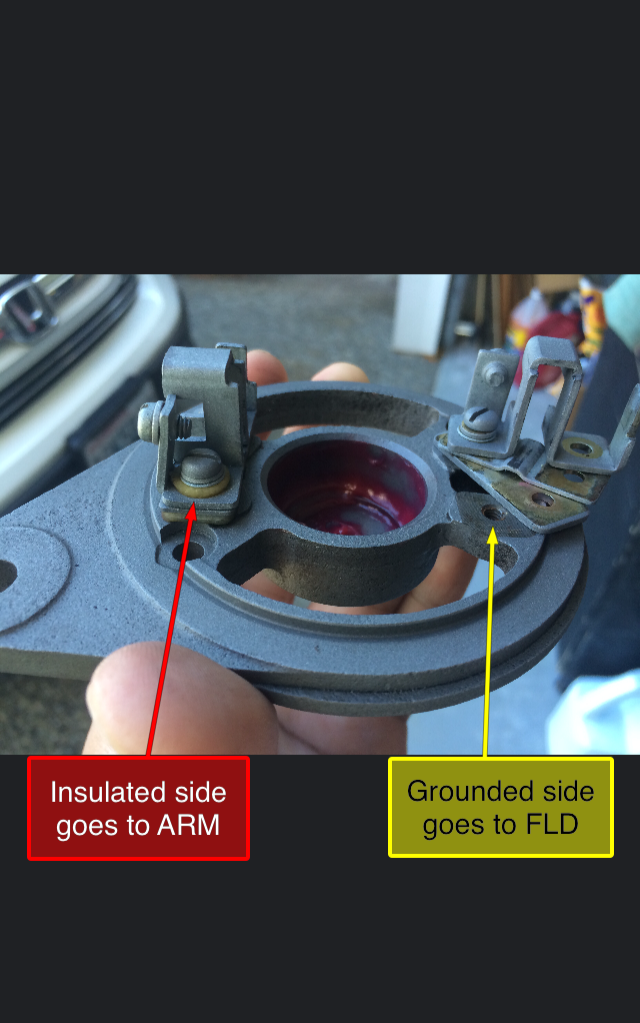
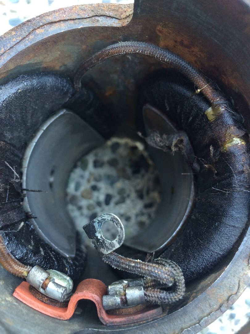
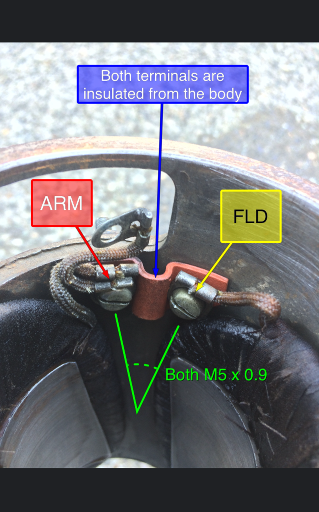
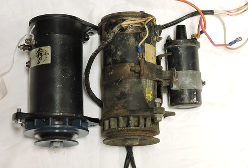
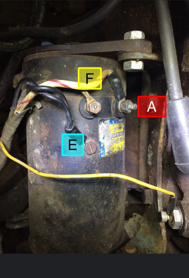
So to start, here is what my generator looked like prior to everything, I labeled the terminals just to be clear what goes where:
Image

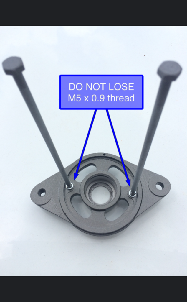
DO NOT throw anything away! Something I thankfully found out right away. The generator is pretty much ALL metric. In addition to this, ALL the terminals and the two long bolts holding everything together are M5 x 0.9 thread pitch. This is difficult to nearly impossible to find. So unless you'd like to drill and tap new threads, I suggest keeping everything in a safe place.


deerio
Posts: 92
Joined: Wed Oct 22, 2014 11:43 pm
Car: '63 L320
Location: Seattle, WA

Post

Unfortunately I never got to take pictures of the armature assembly so that part might be difficult to imagine. Once the generator was unbolted from the engine, I removed the two long bolts located on the commutator side (facing the firewall) of the assembly.

The ends of the body should easily just pull off or might need a slight tap with a rubber mallet. You'll basically end up with 3 parts, the commutator side cover, the drive-end cover, and the field coil body.

Here is what the commutator side looks like after I went over it with some glass bead:
Image

Pay special attention to the two brush holders. The INSULATED holder is located by the mounting bolt. The two end covers only mount to the body in a single orientation and is located by a small pin.

deerio
Posts: 92
Joined: Wed Oct 22, 2014 11:43 pm
Car: '63 L320
Location: Seattle, WA

Post

As far as brushes go, I went to a local alternator shop and just got something close in size and just used a file to get them to the size I needed.

The old brushes were worn to say the least:
Image

I did insulate the copper wire using some heat shrink then re-soldered the ends. I don't know if it's needed, but I did it anyways?

deerio
Posts: 92
Joined: Wed Oct 22, 2014 11:43 pm
Car: '63 L320
Location: Seattle, WA

Post

So on to the drive-end side of the generator.

Here is what the cover looks like after I took off the pulley:
Image

In order to take off the pulley, I just removed the nut and lock washer. Then the pulley should just pull off or might need some taps with a rubber mallet as well. It is located in place with a woodruff key and spaced away from the cover by a spacer:
Image
Dont mind the little magnets on the woodruff key, I just used it to help keep myself from loosing the little thing.

deerio
Posts: 92
Joined: Wed Oct 22, 2014 11:43 pm
Car: '63 L320
Location: Seattle, WA

Post

Once the pulley is off, the drive-end cover would need to be pulled off the armature arm. I just used a generic three arm pulley puller and it came right off.

Inside the cover will be the bearing assembly that is retained by a spring clip of some sort. I popped out the clip with a small pick and the bearing just tapped out with a socket.

Here is what the inside looks like without the bearing stuff:
Image

Notice the really small locating hole mentioned earlier?

deerio
Posts: 92
Joined: Wed Oct 22, 2014 11:43 pm
Car: '63 L320
Location: Seattle, WA

Post

For those interested, here is what the inside of the field coil body looks like:
Image

Notice how the terminals are insulated from the body itself:
Image

I replaced the ARM and FLD terminals with M5 x 0.8 machine screws instead since they are readily available in that thread pitch. Plus, I was also able to use nylocks to secure them.

deerio
Posts: 92
Joined: Wed Oct 22, 2014 11:43 pm
Car: '63 L320
Location: Seattle, WA

Post

Outside of replacing the FLD and ARM terminals, there was nothing else I did to the body.

So back to the drive-end side. All I did was replace the bearing and used an internal retaining ring instead of a spring clip:
Image

The stock bearing is a 6202 for the drive-end (fan) side. I used a double shielded bearing instead 6202ZZ (Yes I know it's stamped 6202Z, but it's shielded on both sides).

I got the retaining ring from NAPA, I forgot the part number but I'll post it when I get home.

deerio
Posts: 92
Joined: Wed Oct 22, 2014 11:43 pm
Car: '63 L320
Location: Seattle, WA

Post

Now on to the actual armature.

The commutator-end bearing is a 6201. Again, I used a dual shielded version, 6201ZZ. I still used a little bit of grease in the end cap when I put everything back together.

Unfortunately I do not have any pictures of the armature at all, so use your imagination.

In order to clean the commutator, I pretty much bolted everything back together without the body and mounted the assembly into the bracket. I then took a drill and used the M14 nut that holds the pulley to spin the armature. All it took was about 10 seconds using an 800 grit sandpaper held flat against the commutator followed by 1200 grit. And mine looked like new copper! I suppose you don't have to mount it all together and could just rub it by hand, but I tend to do things the hard way :sad:

I meant to undercut the mica by hand but I believe there are something like 28 bars, so I got lazy and didn't bother :inout: . The local machine shop by my house couldn't do it.

deerio
Posts: 92
Joined: Wed Oct 22, 2014 11:43 pm
Car: '63 L320
Location: Seattle, WA

Post

Once everything was cleaned, I just had a machine shop press the commutator bearing and the drive-end assembly into place for me (for free!) since I don't have a shop press around and didn't want to just hammer them back on with a socket.

The spacer should just slide on, and the woodruff key can be tapped back into place. Then the pulley(fan) can also be tapped back on and the lock washer and nut can secure it.

Here is how mine looks after everything was all put together:
Image


So now the important part:
Since everything was taken apart, all residual magnetism is apparently lost. So now the generator needs to be repolarized.

After all the reading I've done, I came to the conclusion that we have an "A" Circuit system due to the fact that our field coil is connected to the insulated brush of the generator.

Something to keep in mind, I personally want mine to be a NEGATIVE GROUND system so my NEG post on my battery is connected to ground, and the POS post is connected to the starter relay. Also, I have the NEG post of my coil hooked up to my distributor (I have no idea if that makes a difference). I also kept the belt off the pulley so I could see it spin.

So once I got my generator wired back up to my voltage regulator, here was my process:

1. I attached one end of a jumper cable to the ARM terminal of the voltage regulator
2. Briefly touched the other end to the BAT terminal of the voltage regulator (SPARKS!)
3. Repeat touching the BAT terminal just to make sure (The pulley should spin clockwise briefly each time it sparks)
4. DONE!

AGAIN, this is what I did and it happened to work for me :gotme

deerio
Posts: 92
Joined: Wed Oct 22, 2014 11:43 pm
Car: '63 L320
Location: Seattle, WA

Post

At some point (not anytime soon) I'll probably take it apart again and I'll make sure to take more pictures, sorry for everything being so vague!

Conner
Posts: 69
Joined: Wed Jun 13, 2012 9:52 am
Car: SRL31101633
1964 L320

Post

Nice job and nice post. There is a lot of very good information here. Thanks for sharing it.

User avatar
Li'l Truckie
Posts: 555
Joined: Thu Jan 02, 2014 9:28 am
Car: 3 x '65 PL 320
1 x '64 PL 320
1 x '63 PL 320
1 x '62 PL 320 - parts :(
1 x '60 PLG-222
and many more Datsuns from 48hp to over 500hp
Location: Leavenworth, KS

Post

Most excellent. Well written and easy to follow along.

Also looks to me as if you have an early type generator based on the pulley cooling blades and thickness. Could you get us measurement of the overall length of the generator, thickness of the pulley, and blade count. Sorry for asking so much, but your parts may or may not work on the later generator. However, they will work on the early 200 series Datsuns - ie my PLG-222, if you have the early longer/slimmer generator. (Pic to follow)

Here we go and forget everything I just said. First chance I have had to compare the two generators so minus a different pulley and a few millimeters difference in the bracket mounting points they both look the same. 320 gen on the left and the 222 on the right -
Image

Li'l Truckie

RG320
Posts: 22
Joined: Fri Jul 24, 2015 10:12 am
Car: 1964 L320 pickup.

Post

I agree, excellent article. Thanks for the link to "How Generators and Regulators Work". I found it very informative. Not ready to work on my charging/ignition system but I am reading these articles for information and to keep up to date to find information as needed. Here are some pics of the incorrect generator in my 64 with home made bracket (that broke easily), and placement blocking the spark plug! Just for grins.

Image

Image

Image

User avatar
Li'l Truckie
Posts: 555
Joined: Thu Jan 02, 2014 9:28 am
Car: 3 x '65 PL 320
1 x '64 PL 320
1 x '63 PL 320
1 x '62 PL 320 - parts :(
1 x '60 PLG-222
and many more Datsuns from 48hp to over 500hp
Location: Leavenworth, KS

Post

RG320,

Might keep the previous owners ID on this homemade job to yourself :facepalm: - wow that's not good at all and could have been catastrophic to the radiator, fan, belt, and hood.

Let's us know when you start "un"- convert the alternator back to a generator and any parts you might need (wiring, OE or aftermarket voltage regulator, bracket, and tension arm). If you decide to keep the alternator you might check out Steve's "Mighty Mouse" thread and the bracket he fabricate for his alternator setup. Very nice work and a downright OE factory look.

Li'l Truckie

deerio
Posts: 92
Joined: Wed Oct 22, 2014 11:43 pm
Car: '63 L320
Location: Seattle, WA

Post

Looks to me like my generator is similar to you 320's but with your 222 pulley? Let me know if you still want any of those dimensions and I'll measure them out when I can.

Really tho, outside of finding out that all those fittings were an unusual thread pitch, there's not much to be surprised about. Thank goodness, cuz I really did not know what I was doing. :eek:

That link to generator systems was a HUGE help clearing things up. No matter what I read, every one had their method of polarizing but no mention of how and why. Practically all of the previous things I read never even took into consideration what kind of circuit our generator system was. So as long as your generator appears to be an "A" circuit like mine, then my instructions are probably ok? Nothing smells like it's burning yet :bigthumb:

User avatar
Li'l Truckie
Posts: 555
Joined: Thu Jan 02, 2014 9:28 am
Car: 3 x '65 PL 320
1 x '64 PL 320
1 x '63 PL 320
1 x '62 PL 320 - parts :(
1 x '60 PLG-222
and many more Datsuns from 48hp to over 500hp
Location: Leavenworth, KS

Post

deerio,

No, do not need measurements, I think I'm good.

Thread pitch and SAE vs Metric - ugh, what a PITA. That's why I have found it so important to mark the nuts and bolts as it is pretty impossible to find some of the non-standard sizes or a tap and die set to rework the threads. For my 222, I have metric and SAE wrenches and sockets everywhere :crazy:

Yeah, nothing is worse than the sight and smell of burning wires and smoke coming from underneath the hood or dash.

Andy


Return to “Datsun 320”