Hello,
I've got a 90 Nissan 240SX - the AC which when working blows quite cold even on the hottest of days INTERMITTENTLY cuts off (compressor) randomly extended periods of time: Might be 20 minutes one day and might be the entire day the next! This problem should not be confused w/ ordinary automatic 'cycling' of the compressor. When it's working it does correctly 'cycle' on and off for extended periods of time.
But I can tinker on it every weekend and never experience a problem but a half hour from home on a hot day - ya never know! There is absolutely no rhyme or reason to it as best I can tell like load or temperature or humidity etc. - rain or shine, it's just a purely random thing.
Since I can't consistently reproduce the problem - what I've been resorting to is process of elimination - trysomething drive a few days or week and see if the problem returns. So far it always does and I'm starting to run out of things to eliminate! So I'm looking for possible suggestions to check out.
What I've done/eliminated so far:
A) Long ago when it first started I checked the charge - I don'trecall the #s but it appeared to be fully charged at the time as Irecall.
B) I 'shorted' the pressure cutoff switch on the drier with a piece of copper - no affect problem still occurs intermittent. Pressure switch is OK
C) I replaced the AC relay (located under air filter) w/ a brand new unit - out $15 and NO affect problem still occurs intermittent.
D) I 'shorted' the thermal cutout switch on the compressor itself - Again, NO effect problem still occurs intermittently.
E) I've gone though all the accessible wires and grounds not thoroughly burried in looms and looked for good clean tight connections and such. Besides the car is in a very clean dry mild environment and zero other electrical gremlins during it's entire 14-years (owned since new). Everything looks super clean - didn't find anything remotely suspicious here.
F) I took out the entire center console and disassembled the HVAC control switch box looking for a possible bad contact @ the on/off switch - nicely engineered control switch w/o a hint of a problem!
??? So where can I go from here to look for a possible problem w/ the system that causes the compressor to kick off randomly and STAY OFF for for extended periods before coming back on ???
What else can I eliminate ???
thanks,
Debugging intermittent A/C (electrical?) problem?
-
yellow_jacket
- Posts: 1355
- Joined: Mon Jan 13, 2003 4:43 pm
- Car: 95 240sx
Only once in the last year was I lucky enough to have been out there w/ the hood raise and a VOM and the thing decided to NOT work. It was then that I checked the voltage to the compressor/clutch - It's been quite a long time since then but IF I recall correctly there was no voltage to it.
It was at that time that I played around w/ the relay and it kicked on and off a few times before it started suddenly working again... So for kicks I replaced the relay but within a few days it was up to it's old tricks so obviously the relay was not the problem and I was back to square one.
What do you mean by the "control unit"?
I have only very limited access to the wiring as it quickly disappears into large enclosed looms - wiring access points I've found/have access to thus far include:1) Compressor/clutch/Thermal switch2) Relay (under air cleaner)3) Pressure Cutout switch4) Center Console AC On/Off switch...all of which have been eliminated in testing process.
Can you elaborate on the location and function of the control unit on a '90?
thanks!
OK I'm again looking at my crappy Chilton's wiring diagram and I see you are referring to THE control unit aka ECCS Control Unit - Yes I see at least 2 connections to it - one appears to be shared w/ sensing the fuel pump - probably this ensures the AC and/or condensor fan operate when the engine is running - since obviously the engine continues to run this one may not be a problem but the other connection could be as it appears to control the relays based on the AC switch...
I'm guessing the control unit is located in the passenger footwell area...?
I doubt the connection at the control unit is a problem as these usually have a large loom w/ a snug multi-connector but will check. It will also be a good place to do further debugging IF I can ever induce an intermittent problem.
I also found a SECOND wiring diagram covering the AC within the same crappy Chilton's book. In the first it looked like the FICD Solenoid was wired in parallel so I dismissed that circuit. In the new diag it looks to be wired in series - that could suggest the FICD Solenoid might be a possible 'hold up' to the compressor if simething is not working correctly there... it's another potential failure point to eliminate at the least. I presume the FICD is some sort of idle compensator for the AC?
Whether it's in series or parallel to the primary AC relay, I CANNOT find the second AC mystery relay whatsoever...
And which wiring diag is correct I dunno...
...and it gets worse - Not only does Chilton not bother to provide a single consistent diagram they dont' even PROVIDE WIRE COLORS!!! How's that for fun?
I'm sorely tempted to wire my own independent AC on/off switch directly to the relay - but before I do that I also need to verify if the condenser fan is cutting off w/ the compressor...
Well I need to go study the second ECCS wiring diag and try to make a judgment as to which if either is accurate.
Yep, in step #F) above I took the center console apart, removed the HVAC control unit and dismantled it fully - it's a nicely engineered piece and I saw nothing apparent wrong with it. Everything was crystal clean and the breaks and connects were solid and crisp w/ no observed connectivity 'resistance'. Further, when the problem occurs it is random and not during a button push or setting change. When the compressor kicks out - no amount of button pushing or fiddling w/ the controls on the dash has any affect whatsoever. Leave it on and wait long enough (usually too long!) and magically it 'works' again.
I will definately look in the kick panel for the 2nd relay and add'l fuses. My wiring diagrams don't agree as to whether the FICD relay is in series or not but it's still worth a looksee regardless!
Also since this appears to be an automatic cycling system not intended to operate the compressor 100% of the time - I'm PRESUMING even though I haven't found it yet on the wiring diagram that there is a temperature sensitive switch in or near the evaporator coil... Can anyone confirm this?
Thanks for the tips! Will check in there for that 2nd relay etc...
-
yellow_jacket
- Posts: 1355
- Joined: Mon Jan 13, 2003 4:43 pm
- Car: 95 240sx
Hello Yellow Jacket,
By "on the box" which box are you referring to? Typically I've found on a cycling AC system there is a thermistor or temperator sensor on the evap coil wired to the compressor relay (I've already found) so 'box' and 'temp relay' is throwing me...?
If I get time this weekend I'll be trying to locate that 2nd relay to check out.
Chiltons rant on:Since purchased new 14 years ago the car has never had a problem that remotely required a manual let alone a FSM. Just normal routine wear things like batteries, struts, one clutch recently - hohum stuff not requiring any book. Recently going thru a used book store noticed they had a bunch of new/unsold Chiltons and since Haynes doesn't make one for it - at $5 (new) I figured it couldnt' hurt at that price. For 20 years I have despised Chiltons and refused to waste anything on them. Even at $5 it's still largely a waste - no wonder unsold copies made there wa to a used bookstore. I think at last after 14 years I've arrived at a time when a FSM IS the way to go especially in the area of wiring diags. It's now on my list of things to keep an eye out for or hunt down here before long. I consider that lost $5 a re-affirmation of my original long standing opinion of CHilton's crappy manuals. Chilton's rant off!
THere - I feel better!
Intermittent A/C problem
This is probably too simple of a solution to your problem. I recognize that "- no amount of button pushing or fiddling w/ the controls on the dash has any affect whatsoever," but my '90 240sx a/c compressor shuts off intermittently (green light and all) when I have the fan on the highest setting, and I have to wiggle the switch half-way between last and second-to-last setting. Good luck.
 Re: Debugging intermittent A/C (electrical?) problem?
I realize this is like waking the dead, but I'm having the exact same problem. I got tired of wasting my weekends going over all the same electrical lines, control unit, relay, etc. so I gave up right at the beginning of winter, but now it's summer again and I'm tired of the surprise sauna moments in the middle of rush hour traffic. SO, I've decided to crack open the A/C compressor relay and fusing the contacts so that the compressor thinks the control unit switch is on ALL THE TIME. Somebody please tell me that my car should be ok OR tell me how to fix the intermittent on-off problem.
Things not to bombard me with (please):
1)I've changed the actual compressor TWICE
2)I've changed the A/C relay FIVE times
3)I've changed the A/C control unit inside the car FOUR times
sometime it does the on-off thing right away after a change and sometimes it tricks me into thinking I fixed the problem until two or three or seven days later.
-
compactfean
- Posts: 2602
- Joined: Thu Dec 03, 2009 10:28 am
- Car: 89 240sx s13 sr gt3071r 23psi
B14 sentra ser sr20de-t 7psi
daily - Location: reno nv
Re: Debugging intermittent A/C (electrical?) problem?
Simple fix...wire the AC pump to an on off button?
-
hellboy006
- Posts: 58
- Joined: Sat Feb 24, 2007 6:03 am
Re: Debugging intermittent A/C (electrical?) problem?
Im having the same problem, Ac works fine for a while then the compressor kicks off like normal but just decides not to kick back on & the air gets hot.. the green AC light stays on the whole time. It does this at completely random times & stays off for various lengths of time.. Anyone found a fix for this yet?
-
compactfean
- Posts: 2602
- Joined: Thu Dec 03, 2009 10:28 am
- Car: 89 240sx s13 sr gt3071r 23psi
B14 sentra ser sr20de-t 7psi
daily - Location: reno nv
Re: Debugging intermittent A/C (electrical?) problem?
I don't know if this applies to anyone but in doing a ton of research on my wiring harness for my sr20det I found that it has an ambient air temp sensor input on the engine harness. With this working correctly it makes it so that if it is 45° or below it will not allow AC pump to kick on. So if you guys have one maybe the sensor is going out or is too close to the accumulator which gets damne cold) and turning it off? Just an idea.
-
Wc240

- Posts: 899
- Joined: Tue May 12, 2009 8:58 pm
- Car: 89 Nissan 240SX
97 Nissan 200SX
91 Nissan 240SX ka-t
06 Scion xB
2000 Nissan Frontier - Contact:
Re: Debugging intermittent A/C (electrical?) problem?
had a car do this a long time ago, might be worth checking, when it does shut off, see if your evaporator core is freezing, sometimes the TXV can get mest up and not shut off your compressor until the evaporator froze.
Re: Debugging intermittent A/C (electrical?) problem?
Found this out on the interwebs, can anybody tell me or find a pic that demonstrates what and where this "Amp" is?
"I've had my S13 for 2 years now, & have always had the problem of intermittent A/C operation- where for no apparent reason would run when it wanted to when the A/C button was pressed, or would not.
When it did run, would shut off anywhere for 5 to 20 mins. or so.
Traced the problem to the Thermo Control Amp. It was plugged in, but if you jiggled the harness wire around, would instantly start or stop the compressor.
Hope this helps someone
Kevin"
Re: Debugging intermittent A/C (electrical?) problem?
I found it! It's behind the glove box, and when I jiggle the plug connected to it, BEHOLD click on, click off a/c chaos!
Here's a pic of somebody screwing up their a/c forever but they've pointed out the Thermo Control Amp nicely:
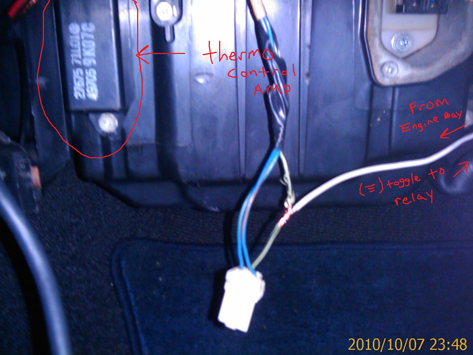
*If and when this picture disappears: The Thermo Control Amp is located behind the glove box and can be accessed by either releasing the glove box stoppers and letting the whole thing hang all the way to the floor or removing the whole dash if you happen to have clumsy, sausage-like fingers (like me).
It seems that the plug doesn't fit as snugly as it use to or the connections don't make as good a contact as before. I drove around for 20 minutes and whenever the a/c would cut off, I'd reach over, jiggle the wire and the a/c would come back on. SO, I've put battery pole protector inside the three holes of the male plug (you'll know what I'm talking about when you see it.), it's conductive and protects from further corrosion so it should do the trick. If you can get your hands on some conductive lube it should work better but I'm working with what I got since it's Memorial day weekend and everything is closed. Remember not to overdo it with the lube or conductive goo since you might create an electric bridge between the three wires and short something out making a whole new issue.
P.S. somebody owes that Kevin dude a b/j (not it).
Here's a pic of somebody screwing up their a/c forever but they've pointed out the Thermo Control Amp nicely:
*If and when this picture disappears: The Thermo Control Amp is located behind the glove box and can be accessed by either releasing the glove box stoppers and letting the whole thing hang all the way to the floor or removing the whole dash if you happen to have clumsy, sausage-like fingers (like me).
It seems that the plug doesn't fit as snugly as it use to or the connections don't make as good a contact as before. I drove around for 20 minutes and whenever the a/c would cut off, I'd reach over, jiggle the wire and the a/c would come back on.
P.S. somebody owes that Kevin dude a b/j (not it).
-
hellboy006
- Posts: 58
- Joined: Sat Feb 24, 2007 6:03 am
Re: Debugging intermittent A/C (electrical?) problem?
Sweet! A lead! Ill check this out & report back here!
..Oh & NOT IT!
..Oh & NOT IT!
-
hellboy006
- Posts: 58
- Joined: Sat Feb 24, 2007 6:03 am
Re: Debugging intermittent A/C (electrical?) problem?
Finally got around to checking this out today.. The connector seemed clean & tight but i took it apart & cleaned it anyway.. put a little battery terminal goo on the male connectors probes & put it back together. I also wrapped a zip tie tightly around the whole thing including the connector to hopefully keep in nice & snug in its receiver. I cruised around in town & out on the highway for about 30 minutes or so & the AC worked correctly the whole time. But since this was an intermittent problem only time will tell if its truly fixed.
I also cleaned the end of the thermal probe thingie
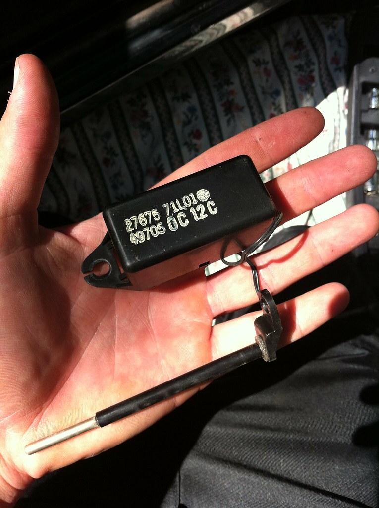
If you look closely in this picture you can see the zip tie

I also cleaned the end of the thermal probe thingie
If you look closely in this picture you can see the zip tie
-
hellboy006
- Posts: 58
- Joined: Sat Feb 24, 2007 6:03 am
Re: Debugging intermittent A/C (electrical?) problem?
Its been 4 or 5 months since I did this & my AC has worked perfectly ever since..
-
92sxCalifornia
- Posts: 6
- Joined: Sun Jul 13, 2008 1:10 pm
- Car: 1992 240SX
Re: Debugging intermittent A/C (electrical?) problem?
My intermittent AC problem was also due to the thermo control amp. In my case, there were bad internal solder joints that were easily remedied by resoldering. Also, the button assembly can suffer burned traces, also fairly easy to resolder so don't buy a new button assembly unless you rule out repair. My '92 AC runs perfect in 2013 and has never needed freon.