'64 320 Clutch Replacement +++

1962-1965 Datsun L320 and NL320 forums - The truck that started it all in the US. All 320-specific topics and discussion can be found here.
User avatar
Li'l Truckie
Posts: 478
Joined: Thu Jan 02, 2014 9:28 am
Car: 3 x '65 PL 320
1 x '64 PL 320
1 x '63 PL 320
1 x '62 PL 320 - parts :(
1 x '60 PLG-222
and many more Datsuns from 48hp to over 500hp
Location: Leavenworth, KS

Post

Hey 320 Fans,

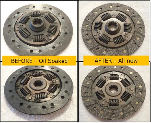
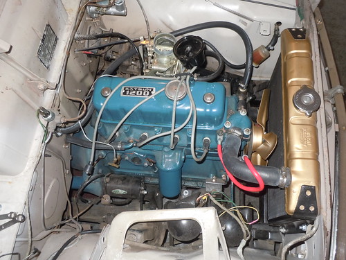
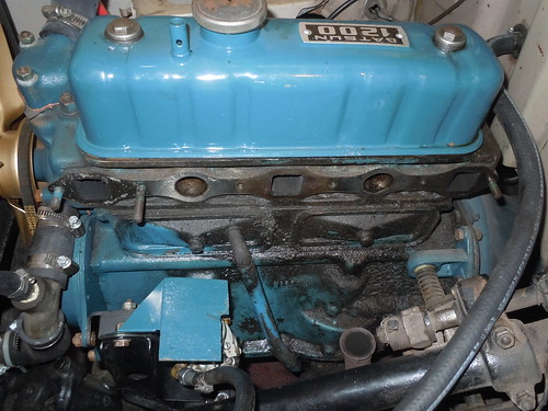
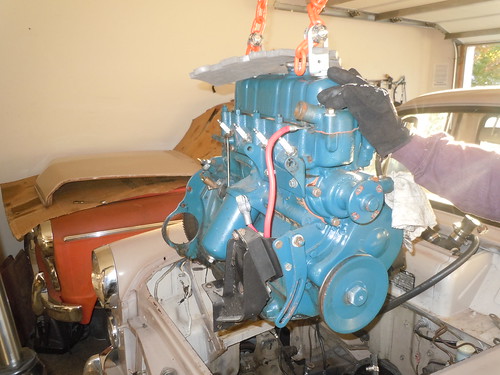
Li'l Truckie here. I spent much of the last two days prepping the '64 320 for a new clutch, plus some other much needed maintenance. So this thread and series of post will concentrate on everything you need to know (hope I don't forget something) about replacing the clutch and other maintenance you could and probably should do since you have to pull the engine, transmission, radiator, and drop the drive shaft.

Image

At this time the grandiose plan now is to replace all the seals and gaskets on the engine (more on this one later!) and transmission. I plan to make a few improvements to the E1 -

- Front timing cover from a MGA to do away with the graphite rope seal-don't know if this will work yet, but should.
- All new manifold studs - so no more bolts
- Maybe a few more - need to see if the parts work
Image

I have already replaced a few gaskets and seals, but will still provide the part numbers and information on where you can get these. And yes there are a few gasket that will require some DIY patience and skill. So if you have not already done so send off get yourself a catalogue for the MGA (55-62) and one for the Sprite/Midget from both Victoria British in Lenexa, KS and Moss Motors out in Goleta, California. Yes, they both have digital catalogs on line, but I find it extremely helpful to have the paper copy to look at too.

http://www.victoriabritish.com/
http://www.mossmotors.com/?gclid=CJPAiJ ... aQodC54Axg

Okay, let's work up the parts list from front to back / top to bottom (all part # are from Victoria British)

AS OF November 25, 2014

ENGINE-
- 1-722 Timing Cover Gasket MGA (confirmed - this is the one you want)
- 1-781 Gasket, Front Cover - yes replacing this pain in the butt gasket and front main seal.
- 14-606 Oval Washers ( I like the oval better than the circle washer - nice option, but they are .95 cents each and there are quite a few required, ca-ching)
- 12-5713 This is a 42 piece (14 x 1/4 bolts, 14 x star lock washer, and 14 x flat oval washer) from the Sprite/Midget catalog price at $6.95. Quick math tells you this is the way to go for new hardware for your timing cover and oil pan. Two kits will get new hardware for both.
- 1-496 Thermostat Gasket (might need to make the holes just a little bigger)
- 0-151 Valve cover grommets (get new ones!)
- 0-150 Nut cap (this is the valve cover nut)
- 0-149 Cup washer for grommet
- 1-483 Valve cover gasket (this will/may not work on the 6 x screw Datsun 1200 valve cover)
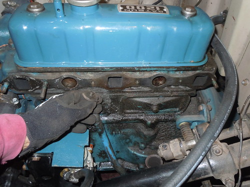
- 1-729 Exhaust manifold gasket
- 12-4312 Exhaust manifold stud (you want all long ones, but short studs (12-1695) are available) replace them all!
- 12-1695 Exhaust manifold stud, short. This is for the very front and back studs for the manifold. If you go with these you cannot use the thick yolk-washers. I have this set up on my one 320 and just had my son tack-weld two washer together - works fine.
- 6-303 Yolk washer (you will want 6, but will need to cut/grind the two outer ones down a little so the do not over hang the exhaust manifold in the front and back)
- 12-356 Brass manifold nuts (You want brass! Not steel zinc coated ones that rust, also available at your local hardware store)
- 1-723 Side cover gasket -cork (need two)
-12-4106 Fiber washer for side cover bolt (need two, just get these and do not waste your time looking for these at your hardware store)
- 1-666 front/rear Main bearing seal (yeah baby, the most oil prone seal to fail has the number of the beast! how fitting) oh, you will need two.
- 1-725 Oil pan gasket (just need to snip the on inner back corner, perfect fit)
- 1-782 Back cover gasket

Engine DIY gaskets-
-Water pump - inner and outer
-Oil filter housing if you have a later MK III or IV E1 with bolt on oil filter housing - The E1 MK I and II have a cast oil filter housing. More information on this here -http://datsun320.com/ - just scroll down to the bottom.
-Distributor Gasket
-Water outlet gasket (the return from the heater core)

Okay, that about does if for engine seals and gaskets- make sure to check this list as I will make continued updates to it.

Transmission Gaskets -

- 9-1018 Clutch Lever Boot (tight fit, make sure you use some silicon spray)
- 1-7411 Front Cover Gasket
- 1-7001 Side Cover Gasket
- 4-322 Release Bearing - perfect match. Tracking this is not a gasket.


National # 710324 Rear output shaft seal - local auto parts store
Timken # 471466 Forward and Reverse Cross shaft seal - local parts store

Okay that's about it for now. Again, I'll continue to update the parts list so check this post ever so often. Especially for the part numbers and links for the clutch disc, pressure plate, and release/throw-out bearing.

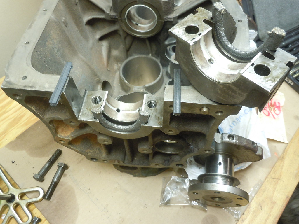
More info and a lot more pics tomorrow evening - engine and trans came out this afternoon, just need to good light for pics.

Cheers
Li'l Truckie


User avatar
Li'l Truckie
Posts: 478
Joined: Thu Jan 02, 2014 9:28 am
Car: 3 x '65 PL 320
1 x '64 PL 320
1 x '63 PL 320
1 x '62 PL 320 - parts :(
1 x '60 PLG-222
and many more Datsuns from 48hp to over 500hp
Location: Leavenworth, KS

Post

A little hot in the city tonight 320 Fans, like 81 outside, time to cool back down,

Okay, a long week burning up the phone and emails, with no news. Well, okay, a little bad news. So if you scour eBay long enough almost anything will come up. Say like a 180mm, 10 spline, clutch disc. Okay, so its from a Fiat. Made in Italy. A boot that is best entered from the top, so says history. Yeah, well it didn't work. Wish it did. As you can see from the pic below the input shaft center measures 3/4 inch and we need a 1 inch center. So we will keep looking. Yes a Sprite/Midget works, but it only has 4 compression springs vs the 6 you see here. So we have a line on a clutch disc, just not the one I would like.
Image

So let's start turning wrenches! :woot: Time to start the disassembly process. After removing the battery the first item I like to remove is the complete distributor assembly. Pretty simple. Might want to start by taking a few pics of the distributor assembly and the routing of the wires and vacuum line. Its probably still best to tape and mark each spark plug lead. Once this is complete you might want to start by removing the vacuum line first, being careful bending this out of the way. I actually like the more challenging way of removing from the carburetor, but its your call. Just be careful with the vacuum line and do not crimp the line. The brass fitting on the distributor is a 3/8 inch while a 10mm (let me double check this one, metric is a much better fit) works better on the carburetor side.

Image

With the vacuum line out of the way go and the spark plugs marked, go ahead and pop the leads off of the spark plugs and lay out of the way. If your distributor is somewhat dirty you might leave the cap on and loosen the locking plate screw or remove the 2 x 7/16 bolts holding the assembly in place. With either one of these complete it pretty easy just pulling the distributor out of its well. For safe keeping until your are ready to clean it up, let's put the distributor in a shoe box or like container and on the shelf out of the way.

While we are on this side of the engine let's move onto the generator. First things first! Mark the wires properly and take a few pictures for later reference. The generator is not as delicate apart from the B and F armature leads. So be careful here. Okay, depending on who drilled the hole for the B and F armature leads and the ground post at the Hitachi Electric Plant 50 some years ago, you might have these three connections any where from the top inside by the head all the way over and down underneath by the two horns. So you may want to rotate the generator down or up to get at these wires, connections and nuts a little better. Regardless of their position (I have them in various locations), you might want to release the tension on the swing arm/adjusting arm and then move to the two nut/bolts on the engine block mounting bracket next. All of these should be 1/2 inch nuts/bolts. Take care to properly mark the nuts and bolts on the swing/adjusting arm and these might still be threaded (and not striped out over the years) through the one mounting bracket on the front of the generator. Once all three of the nut/bolts are loose secure the generator in an up position or press firmly all the down and let move on to disconnecting the leads. Yes, now is a good time to also remove the fan belts and get it out of the way.

Image

If you have yet to ever remove the generator armature leads and ground lead, I highly recommend that you grab two wrenches, one for the top nut and one for the bottom nut to keep the lead in place while removing the top nut. This is to prevent the armature lead from twisting off of the wiring inside the generator. My top nut is snug, but I still secure the bottom nut at first and I'm pretty sure this is why my generator is in the shop for an extended period - repair a broken/disconnected wire lead.

Once the wires to the generator have been safely removed, go ahead and remove the generator from the engine block mounting bracket and the swing arm. I'd recommend taking the engine mounting bracket and the swing arm off and put these together with the generator in its own box with the nuts and bolts for safe keeping and cleaning later.

If you have never had your generator looked at by a reputable shop, now might be a good time to get it cleaned up on the inside, new brushes installed, and bench tested under load. Better yet is to take your generator and voltage regulator (if you are still sporting the OE Hitachi voltage regulator) and have them bench tested as a set and make any adjustment at the same time. A local shop will/should have the necessary equipment to test the two as a set.
Image
If you need help with this let me know / PM. I have taken 8 Hitachi Voltage Regulators and a few generators from my 320s and 222 down to Big Glenn for bench testing. Yes, adjusting a voltage regulator is becoming a lost art and many shops will not/do not know how to do it. Its call "Solid State". Very simple - it either works or it doesn't. In case of the latter, you just buy an new voltage regulator. But we digressed. Cost to Big Glenn is about $10 for the two. Takes about 10 -15 minutes and I'm on my way again.

Image

Okay, that's about it for tonight. I'll try to write some tomorrow and we will remove the starter, the pain in the butt horns, and then move over the intake and exhaust assembly.

Let me know if you have any questions or if I forgot something.

cheers,
Li'l Truckie

User avatar
Li'l Truckie
Posts: 478
Joined: Thu Jan 02, 2014 9:28 am
Car: 3 x '65 PL 320
1 x '64 PL 320
1 x '63 PL 320
1 x '62 PL 320 - parts :(
1 x '60 PLG-222
and many more Datsuns from 48hp to over 500hp
Location: Leavenworth, KS

Post

Okay 320 it's time to play some catch up!

Statistics in Education is over, so no more t-test, F distribution, or chi-square equations or nightmares.

So some good news first, err....at a price. Generator is back to the tune of ~$160 and some change. That's $35 for a donor generator that caught fire on the Jimco Starter/Generator Test Set, and $125 to strip down the donor generator and rebuild the original.

Also, the Clutch disc fiasco is over as for a mere $50 plus tax, Kay Cee Clutch Rebuilders in downtown KCMO rebuilt the original disc - totally amazing. My pressure plate is good, but a rebuild quote of $80 plus tax and you will get back a surfaced pressure plate with correct height shims and new springs if needed. Needless to say the little 180mm clutch disc from the 320 got quite a few laughs sitting on the table with those 2 1/2 to 3 feet clutch discs from some Caterpillar and mega Volvo Dumper.
Image

Okay, so let's get that starter out.

Again, if you have never taken out the starter before or replaced the power cable two wrenches are a must on the nuts securing the cable. I had a short in my one starter probably because I did not secure the inside nut and twisted the complete screw terminal. Starting price just to look at it was $55, add another $55 to fix it, that's if it could be fixed and then add tax - uh, no thanks. So with the outside nut removed, gentle remove the power cable and tuck it out of the way.
Image
Only two fine tread bolts secure the starter through the back plate to the transmission housing - one top and one bottom. With the distributor out of the way it's pretty easy to get at the top one while you might find it easier to crawl underneath to get the bottom one. With both bolts out the starter will wiggle free of the flywheel ring. Make sure to inspect the starter teeth. Replacement starter teeth are available from VB (part # 8-42790 for 9-teeth) and MM. Or you might just go with new starter (VB part # 8-155) if yours is tired out or not working properly.
You should have also just remove a ground cable running from the bottom starter bolt (usually) over to the inner frame rail. Make sure to clean this up a bit and replace if it does not look too serviceable.

Okay, with the starter out of the way let's remove the horns. Remove the two green power wires and try not to move the connectors up and down too much as they might break off. The two bolts are a little tricky to get at so have patience. I absolutely hate removing them, but necessary as the motor mount will not clear the horns once you start hoisting it up and out.
Image
Careful removing the two mounting bolts as one secures the horn ground wire.

Okay, so this should be all we have to remove on the right side of the engine. We'll move over to the left side and start removing the intake/exhaust manifold as a complete unit, remove the shift linkage and disconnect a few other things.

Parts list has been updated so might take a look up top.

Cheers,
Li'l Truckie

Conner
Posts: 69
Joined: Wed Jun 13, 2012 9:52 am
Car: SRL31101633
1964 L320

Post

Thanks for the update. Really good information here.
Your horns look a lot different than mine, which I assumed were stock (maybe not).

Here are mine. My truck is a 1964.

Image

And cleaned up:

Image

User avatar
Li'l Truckie
Posts: 478
Joined: Thu Jan 02, 2014 9:28 am
Car: 3 x '65 PL 320
1 x '64 PL 320
1 x '63 PL 320
1 x '62 PL 320 - parts :(
1 x '60 PLG-222
and many more Datsuns from 48hp to over 500hp
Location: Leavenworth, KS

Post

Thanks Conner,

These are the OE/stock Miyamoto high and low tone horns. I have seen these referred to as the "Lucas type"...sure. The bulb makes it hard to get at the bolts holding them to the mount. Not to mention you have to get under the battery tray with a socket and extension. Just remember to put these on first once you have the engine back in.....I didn't the one time and it was frustrating trying to a contortionist with arms, hands, and ratchet under the generator.

I also checked the fleet today and have this type horn in four of the six 320. I have a different set than these and the ones you have pictured (but similar to your set) on my late '65 with floor shift, and the one '65 has the type found in the later model 510. Pretty sure these are replacements. I would say yours are OE/stock from the looks of the before photos. I be curious to know if there is a manufacture label on them.
Image
I think its safe to say that Nissan probably used more than one type of horn supplier. Thanks for the pics. I reference these pics on the "What year is my 320" thread.

v/r
Andy

User avatar
Li'l Truckie
Posts: 478
Joined: Thu Jan 02, 2014 9:28 am
Car: 3 x '65 PL 320
1 x '64 PL 320
1 x '63 PL 320
1 x '62 PL 320 - parts :(
1 x '60 PLG-222
and many more Datsuns from 48hp to over 500hp
Location: Leavenworth, KS

Post

Okay 320 Fans, time to keep moving along,


So let's move over to the left hand side of the motor and remove the intake/exhaust manifold and carburetor, drop the exhaust down pipe and get at the shift linkage.
Image

Don't think is really matter much where you start, but I like to remove the Accelerator and Choke cables first.
CAUTION: The Nikki Carburetor has a mix of Metric and SAE nuts and bolts, so you might want to make sure you have a tight fit with the closed in wrench if it seems a little hard to loosen the nut/bolt.
At least on this carburetor the nut and bolt securing the accelerator cable to the throttle lever is 5/16 inch. While the nut with the hole for the choke cable is an 11/32 inch.
Image
A nice Number 2 flat tip should do you for the two screws securing the cables. That's why I have two sets. One set of screw drivers for me and a set I do not care what happens too for the son.
Once these two cables are free of the carburetor, go ahead and fish them through the brake/clutch lines of the fire wall to keep them out of the way.

The last item to remove is the fuel line. You either have the OE metal line coming up from the fuel pump or a simple rubber hose with hose clamp. Might want to put a rag or two under the carburetor to catch any fuel that might leak out or spill once you remove the fuel line. Otherwise that's it for the carburetor. I'd recommend just leaving the vacuum line attached to the carburetor and remove it once the intake/exhaust manifold is removed.

Okay, next is the exhaust clamp securing the exhaust down pipe to the exhaust manifold. Good Luck. Hopefully, the previous owner(s) left this alone or reused the OE clamp as it has the brass nut. If that's the case it will be a little easier to remove. Two 1/2 inch wrenches is all you need to remove the two nut/bolts securing the exhaust pipe. Depending on position of the clamp you may just want to get it a little loose and spin the clamp a little to get a better angle on the two nut/bolts. Strongly recommend mechanical gloves working down here as you are competing for space with the gear shift linkage. So space is tight with a lot of bare steel to catch/dig the back of your hands into. You might have to separate the nut/bolt to get the clamp off the exhaust pipe/manifold.

Finally, we are ready remove the intake/manifold assembly. Pretty simple at this point. Just five nut/bolts and it will peel away. I have had a combination of nut/studs and bolts securing the assembly to the head, but have had no issues with stripped out nut/bolts or breaking them off in the head. So hopefully this will be uneventful for your. Pretty sure they are all 1/2 inch nut/bolts. A ratchet with a 3" extension and socket should suffice to get the middle three nut/bolts off. You want to loosen all the nut/bolts evenly especially once the are all loose to avoid dropping the assembly and possibly damaging something (like the fuel pump we have not removed). So with the intake/exhaust manifold assembly removed we can now get at the shift linkage.
Image

Okay, we'll call it a night for now as I cannot locate the shift linkage photos that I want and we'll pick up again tomorrow evening.

Enjoy your Thanksgiving!
Li'l Truckie

User avatar
Li'l Truckie
Posts: 478
Joined: Thu Jan 02, 2014 9:28 am
Car: 3 x '65 PL 320
1 x '64 PL 320
1 x '63 PL 320
1 x '62 PL 320 - parts :(
1 x '60 PLG-222
and many more Datsuns from 48hp to over 500hp
Location: Leavenworth, KS

Post

Hey there 320 Fans. Looking for some help with this one.

I know we are jumping way ahead in this thread, but looking for some quick help/advise. So here's the issue(s) - the rear main seal.....ugh......
Image
As you know this is the primary reason for pulling the engine/trans on the '64. Failure of the rear main seal resulting in an oil soaked and slipping clutch disc and glazed over flywheel.

In order not to screw up things on the E1 from the '64, I pulled out the crate J13 to look things over before making any costly or irreparable mistakes to the E1. Looks pretty simple and I have conceded that I will need to pull all main bearing caps and pull the entire crank out about 1 inch to get in the new Graphite Rope seal and that it will take two pieces of the graphite rope seal. I know which groove it goes in from the pics, but the question is ---

Where to cut the two rope seals for the best seal? 1/2 and 1/2 or maybe at 1/3 top and 2/3 bottom?
OR
Go with a one piece graphite rope with the two ends meeting at the top on the crank/upper bearing? I can get the 3/8 inch graphite rope seal down at Hanna Rubber in KCMO, so no issue with this.

Either way, I'm listening to the head of household and will undertake this task next weekend
Image

thanks
Li'l Truckie

Conner
Posts: 69
Joined: Wed Jun 13, 2012 9:52 am
Car: SRL31101633
1964 L320

Post

Hey there.
I took off, cleaned, and repainted my valve cover this weekend.
I previously bought a new silicone valve cover gasket from Moss Motors listed for the MGA/MGB/MGC (same part for all three models). The gasket might be hair small when I fit in inside the valve cover, but I think it will work. It may have shrunk a little in the cold garage overnight. Anyhow, my truck is a 64 with the six machine screws that mount the valve cover to the head. The gasket is for a valve cover like yours, i.e. without the screws. I was thinking of fixing the gasket to the valve cover and then drilling some holes through the gasket for each machine screw.
Sound like a good solution or not?

Did any of these British engines come with the valve cover attached by six screws?

Thanks.

User avatar
Li'l Truckie
Posts: 478
Joined: Thu Jan 02, 2014 9:28 am
Car: 3 x '65 PL 320
1 x '64 PL 320
1 x '63 PL 320
1 x '62 PL 320 - parts :(
1 x '60 PLG-222
and many more Datsuns from 48hp to over 500hp
Location: Leavenworth, KS

Post

Conner,

I would go with eBay first. The guy down in Mexico occasionally list the 6 x screw valve cover gaskets - just not at this time. About $6-8 and then add postage.

Sorry no. No British BMC B motor car used a 6 x screw valve cover.

I guess you could adhere additional gasket material to the inside of the valve cover gasket and then drill your hole. I just do not know how well this will hold/seal. You might tear up the gasket with the drill bit because of the two different types of material - cork gasket and the sealant.

Silicon - yeah, I have had bad luck with these. First experience I got the wrong size, but still tried to stretched it, used binder clamps and attempted to adhere it to the valve cover - utter fail :facepalm: Second time was with the correct valve cover gasket and I just could not get it to adhere to the steel valve cover - not matter how well I cleaned the valve cover.

Other options is to get one of the stamped steel BMC B motor valve covers off of eBay and simply paint over the "MG" logo or look for a two bolt E1/J13 valve cover - if you can find one advertised.

Best bet is improvise if an emergency and wait for eBay - probably not what you wanted to here.

Andy

User avatar
Li'l Truckie
Posts: 478
Joined: Thu Jan 02, 2014 9:28 am
Car: 3 x '65 PL 320
1 x '64 PL 320
1 x '63 PL 320
1 x '62 PL 320 - parts :(
1 x '60 PLG-222
and many more Datsuns from 48hp to over 500hp
Location: Leavenworth, KS

Post

Okay 320 fans, back to where we left off with this project.

TRANSMISSION LINKAGE Removal - easier said than done. So grab the rubber mat / folded over carpet/cardboard and roll up a towel it's time to feel your age!

Before your start this task make sure your transmission is in neutral and put down a chalk block! :yesnod As once the linkage is removed from the shift levers its pretty tough to move the forward gears into neutral and your project will not roll without pushing in the clutch. So once in neutral and a tire chalk we can start with this task.

If you have not done so already now is a good time to remove the bench seat from the floor mount. There are 4 x 1/2 bolts, two either side that secure the seat to the floor mount. Once removed get some help and remove the seat from the cab. Don't neglect to put this in a safe place as it is easy to mess up the threads on the studs if you lay it flat on the concrete and start moving it around to get it out of the way of your next task.

Now it's time to get comfortable as there are a total of 13 x 7/16 inch bolts that secure the cover to the floor board. This is where the rubber mat for the knees and towel for the rib cage come into use.
Image
If you still have the OE black cardboard and mohair sound/heat insulation with the rubber trim on the fire wall be careful remove bolts 1-5 as these are underneath the insulation that is prone to crack and tear after 50+ years in place. I have yet to have any issues removing these bolts. 6 sided socket with 4 inch extension with breaker bar and some down ward pressure should do the trick. If your bolts are rusted, highly likely for numbers 7-12, plan on replacing these. Washer and lock washers should clean up on the wire wheel.

With all 13 bolts remove, grab yourself a paint scraper/steel putting knife and gentle loosen 50 years of dirt, rust, oil, and grim and start to pry the tunnel away from the floor board. Again be careful of the insulation on the firewall. Might be a good idea too take your putty knife and run in between the top of the transmission tunnel and the insulation to make sure they are not stuck together, go easy. Once you get the tunnel separated from the floor board, lift the back end first and pull down and back. This should prevent you from pulling it straight back and pulling the insulation off of the firewall.

Once the tunnel is removed you can get a better view of the side shift linkage. The lever closest to the engine is the reverse lever/linkage with keeper spring and the one at the back is the forward lever and linkage. Reverse is held in place with a cotter pin to the reverse lever. The forward linkage is a little more complicated held in place with the pin-ball and polyurethane seat ball-pin and crossed steel threaded block-thrust washers. You will also see the oil soaked speedometer cable half way down on the transmission rear extension.
Image
On a side note - if you still have the rubber boot on the forward shift linkage and the leather washer on the reverse linkage chances are your transmission has never been removed - congrats!...But don't be surprised if it just crumbles away :frown:

Okay, before you start removing "stuff" take a few pictures of your linkage and how it goes up into the engine compartment and note the placement of the reverse and forward linkage and how they attach to the column shift assembly. Reverse to the reverse gear selector lever for reverse) and the cross-shaft assembly for the forward linkage.
Image

Removing the reverse linkage from the reverse lever is simple enough, just remove the cotter pin and push the linkage out of the lever. Save what you can as far as the leather washer, steel washer and cotter pin are concerned you need these to purchase replacement parts, but we will not reuse them.

Alright, the forward linkage is a little more tricky. I like to remove the cotter pin from the linkage and then remove the crossed steel threaded lock washer from inside the linkage bell. I have yet to have any issues removing the this threaded washer. Just use a large screwdriver and remember lefty-loosy/righty-tighty. What you want to be careful of is apply too much pressure to a seized threaded washer and popping the linkage off of the ball pin that is attached to the forward selector lever. Once you the threaded washer just out of the linkage bell housing you can wiggle the linkage a little and remove it from the ball.

While you are still half in/half out of the cab, go ahead and remove the speedometer from the speedometer pinion and secure the cable so as not to smash it or get it caught on something removing the engine and transmission later. A crescent wrench will work or metric 19mm open end wrench will give you a snug fit.

Okay, time to stand up and stretch and head up to the linkage in the engine compartment. With the carburetor/intake/exhaust manifold assembly removed this is a lot easier task. I would first remove the other end of the reverse linkage. Simply remove the cotter pin and push is out to the gear selector lever attached to the shift column.

As for the forward linkage I like to remove the short ball and rod connector from the shift column forward gear selector lever - that's the half moon looking part. Again, leaving the ball attached to the half-moon selector lever. Simply follow the same steps as removing the forward linkage from the lever on the transmission. Remove the cotter pin and use a big screw driver to loosen the threaded lock washer. Being careful not to apply to much pressure to a seized threaded lock washer - as I did. Because if you do you will damage the cup on the polyurethane washer. So I will need to heat up a ball-pin and repair the side of the cup that I damaged.

From here the only thing left is to remove the cross-shaft linkage and pull out the linkage assembly.
Image
As you can see from the photo the cross-shaft assembly is secured to the steel mounting point that is bolted to the back engine plate. All you need to do is remove those two nut/bolts and the assembly will come free. A quick word of caution is there is some pressure here with the spring-retainer cross shaft. So loosen the nut/bolt together. Don't worry ,nothing is going to go flying out to the engine compartment. Once the nut/bolts are loose and the pressure from the spring relieved the shift assembly and be wiggle out of the engine compartment. Again, take a few pictures of the assembly before totally disassembling it for a thorough cleaning and a quick coat of satin black engine paint. Here's what the linkage assembly looks like all cleaned up and painted - ready for re-install----
Image

I think that will do it for the shift linkage - let me know if you have any questions
Stay warm :ohno: burrr........
Li'l Truckie


Return to “Datsun 320”