I've been following Mike's conversion, decided to tackle my own.
Got the drive swapped out onto the new dizzy.
Running into a few problems - Seems my mount is very different from his, as you can see in these pics.
Hoping someone can shed some light on what's going on here - Do I have a different engine completely? Wrong EI dizzy? Or do I need to start fabbing stuff?
[img]http://www.nicoclub.com/Greg/dizzy1.JPG[/img]
[img]http://www.nicoclub.com/Greg/dizzy2.JPG[/img]
[img]http://www.nicoclub.com/Greg/dizzy3.JPG[/img]
[img]http://www.nicoclub.com/Greg/dizzy4.JPG[/img]
[img]http://www.nicoclub.com/Greg/dizzy5.JPG[/img]
[img]http://www.nicoclub.com/Greg/dizzy.JPG[/img]

Need help with EI distributor conversion... Please?

What you have is the early E1 distributor setup. The later E1 had the same setup as the J13-J16. I'm not sure how to go about the electronic distributor setup on the early ones. Maybe Mike knows. Look at the mounting differences in the two scans.
[img]http://i28.tinypic.com/2jeojv8.jpg[/img]
[img]http://i27.tinypic.com/2mzh6o3.jpg[/img]
[img]http://i28.tinypic.com/2jeojv8.jpg[/img]
[img]http://i27.tinypic.com/2mzh6o3.jpg[/img]
I just learned about the difference between the early and the late yesterday or the day before. I thought an E1 was an E1!!
How about a couple of pics of the stock dizzy next to the EI dizzy. What did the EI come out of....I'm used to seeing a hole going up into the bottom to hold the L series adjustment plate.
I wonder what size the hole is in the block if you remove that plate/sleeve.
How about a couple of pics of the stock dizzy next to the EI dizzy. What did the EI come out of....I'm used to seeing a hole going up into the bottom to hold the L series adjustment plate.
I wonder what size the hole is in the block if you remove that plate/sleeve.
-
odpl_AZhitman
- Posts: 31
- Joined: Wed Dec 31, 1969 5:00 pm
OK, good stuff - we're getting somewhere! 
Thanks IMH - I even had that damn printout and never got the hint... I'm a doof.
OK, so now as it stands, I've taken the (22179 in the diagram) mounting plate (also pictured in pic 5), and modded it to slide up over the fatter part of the dizzy housing (the first "step-up", seen in pic 1 and 2.
Now, as Mike said, there's the threaded hole going up into the bottom of the EI dizzy casing... However, when I mounted the plate on the dizzy shaft, there was no way to push the bolt (22204) through, so I cut that little "nub" off (threaded hole and all).
OK, now:
The plate atttaches to the dizzy nicely. However, when I insert dizzy shaft into block, and I feel the drive 'engage', the plate is still 1/8" from the mounting surface of the block. Run the bolts in, and it pulls the plate off the dizzy (almost like a steering wheel puller would do).
SO - If you guys see no other problems with my project thus far, I'm gonna duplicate the plate (making an identical "twin", but without the "loops" for a tightening bolt.... and add it under the current plate, but with a center hole the same diameter as the dizzy shaft. This should take up the 1/8" and allow the dizzy to mount securely.
-
odpl_AZhitman
- Posts: 31
- Joined: Wed Dec 31, 1969 5:00 pm
-
odpl_AZhitman
- Posts: 31
- Joined: Wed Dec 31, 1969 5:00 pm
All connected...
Wiring question, now (keeping in mind this is a positive ground system, not that it should matter for distributor connection):
2 wires off matchbox on EI dizzy were labeled:
"Coil Neg" and "Ignition".
I ran the coil neg to the neg terminal on coil, and the ign to positive battery...
Not starting - Wonder if I have something screwed up?
The position of the module can be changed by reclocking the shaft in the eng that drives the dizzy. I just haven't gotten around to doing mine.
Wiring. The ign connection should go to a switch 12v wire, otherwise, you're running power through your module all the time. The neg is correct. You want to run a 3rd wire to ground. Most of the EI dizzies have a spade term mounted with the screw that holds the vac adv in. Most of the time that an EI dizzy is called bad, it's do to a bad ground.
Finding TDC. Pull plug 1, put thumb over hole as you come up on the timing mark on the crank pulley. If you creates pressure, line the crank mark up with the tab. If it does not, rotate the eng around again....check with thumb as you are coming to the mark. Put your thumb one when you're 1/2 to 1/4 from the mark.
No look to see where your rotor is pointing. Eyeball a reference of where it's pointing. Put the cap on the dizzy and turn the dizzy until you can get one of the plug wire towers lined up. doesn't matter which one, whichever is closer at this point. Put the plug wire for cyl one in that cap tower. Going COUNTERCLOCKWISE, the next wire will be plug 3, then 4, then 2. If everything's hooked up, try starting it. When you get it started, you can check the timing with a timing light. You'll want to be able to move the dizzy so that your desired timing is in the middle of the range of movement. Your clamp setup on the dizzy should allow you to do that easily. In fact, I'd leave that a bit loose while your doing your initial timing.
You can do the test light from batt + to coil neg and crank it...it should flash. The EI module uses transistors as the ground switch for the coil. They'll handle a lot more current than the points, but the coil is simply looking for a grnd to be turned on and off. If you do not have a coil designed for the EI ign, you'll still need to run the ballast resistor....just make sure that you hook up the ign from the side of the resistor that is getting the full 12V. If you hook it up on the output side of the resistor, you won't get enough volts for it to work....at least not well. You're connected to the batt directly right now, so that's not the prob.
I need to go work on my 3 point seat belts I'll check back tonight.
Wiring. The ign connection should go to a switch 12v wire, otherwise, you're running power through your module all the time. The neg is correct. You want to run a 3rd wire to ground. Most of the EI dizzies have a spade term mounted with the screw that holds the vac adv in. Most of the time that an EI dizzy is called bad, it's do to a bad ground.
Finding TDC. Pull plug 1, put thumb over hole as you come up on the timing mark on the crank pulley. If you creates pressure, line the crank mark up with the tab. If it does not, rotate the eng around again....check with thumb as you are coming to the mark. Put your thumb one when you're 1/2 to 1/4 from the mark.
No look to see where your rotor is pointing. Eyeball a reference of where it's pointing. Put the cap on the dizzy and turn the dizzy until you can get one of the plug wire towers lined up. doesn't matter which one, whichever is closer at this point. Put the plug wire for cyl one in that cap tower. Going COUNTERCLOCKWISE, the next wire will be plug 3, then 4, then 2. If everything's hooked up, try starting it. When you get it started, you can check the timing with a timing light. You'll want to be able to move the dizzy so that your desired timing is in the middle of the range of movement. Your clamp setup on the dizzy should allow you to do that easily. In fact, I'd leave that a bit loose while your doing your initial timing.
You can do the test light from batt + to coil neg and crank it...it should flash. The EI module uses transistors as the ground switch for the coil. They'll handle a lot more current than the points, but the coil is simply looking for a grnd to be turned on and off. If you do not have a coil designed for the EI ign, you'll still need to run the ballast resistor....just make sure that you hook up the ign from the side of the resistor that is getting the full 12V. If you hook it up on the output side of the resistor, you won't get enough volts for it to work....at least not well. You're connected to the batt directly right now, so that's not the prob.
I need to go work on my 3 point seat belts
DOH!!!!! I just realized you said it's a pos ground!! The EI dizzy won't work on it! Since your ground is +, the body of the dizzy is + because that's what the block is too. The wire you have connected to the + term of the batt, is simply giving the same 12V+ potential on the input....just like the ground(+) is. The pos side of the coil is actually neg. The transistors will be reverse biased....they won't work. If you try to run a wire from the neg of the batt to the body of the dizzy, it will create a direct short to the pos ground.
I'm really sorry I didn't notice that earlier!! I switched mine to neg ground right off the bat. I'm running a 65A Toy alt.
I guess hang onto the parts to use them if you convert to neg ground??
If you do attemp the conversion...make sure you disconnect your radio antenna and radio. Also disconnect the temp and fuel gauges. The wipers, fan, lights should all work just fine. It's been over a year since I redid my wiring and installed the alt. Maybe one of these days I'll find the info and do a writeup on it.
Again...really sorry I missed that you had pos ground!!
-
odpl_AZhitman
- Posts: 31
- Joined: Wed Dec 31, 1969 5:00 pm
It still grounds through the body...the 3rd wire is just to make sure it has a good ground.
No...sorry it won't work. The points to care which direction the current is traveling. Transistors on the other hand only work one way.
I have at least one option here for you...I'll dig out my old one and see what kind of shape it's in. I was hangin on to it to see if the Pertronix could be made to fit.
-
odpl_AZhitman
- Posts: 31
- Joined: Wed Dec 31, 1969 5:00 pm
Re: Need help with EI distributor conversion... Please?
I'm working on swapping my early E1 distributor to electronic ignition and this thread has been a lot of help. My question is, how are people hooking up the vacuum advance line? My original distributor has a metal vacuum advance line with threaded fittings on either end. The donor distributor has a barbed fitting for a rubber vacuum line. I would like to replace the fitting on the nikki carb with a barbed fitting to I can use rubber vacuum line but I don't know what type of threads those are. I searched the forum and found somebody who said BSPT was used for all vacuum fittings. I looked at the threads on the carb end and it didn't really look tapered and the rough measurements didn't seem to match BSP sizes exactly. It maybe 1/8" BSPP.
Does anybody know for sure?
Dylan
Does anybody know for sure?
Dylan
-
Li'l Truckie

- Posts: 555
- Joined: Thu Jan 02, 2014 9:28 am
- Car: 3 x '65 PL 320
1 x '64 PL 320
1 x '63 PL 320
1 x '62 PL 320 - parts :(
1 x '60 PLG-222
and many more Datsuns from 48hp to over 500hp - Location: Leavenworth, KS
Re: Need help with EI distributor conversion... Please?
DylanFM,
I'll take my extra one with me to the hardware store tomorrow and to Fastenal and let you know what I find. Hate to think the distributor end is SAE (3/8 in) while the Nikki Carb side is metric
Have you thought about going with a distributor system from a MGA? Pretty sure this is a direct fit - no modifications necessary. Electronic ignition is available. I can verify if you would like.
http://www.victoriabritish.com/icatalog ... px?Page=28
Andy
Re: Need help with EI distributor conversion... Please?
If you could let me know what you find I would appreciate it. I hadn't considered using an MGA distributor and I already have most of the parts to do the L20B distributor swap now, so I will continue down that path. Looking at the picture in the link you posted, the drive coupler piece looks different, but it might be compatible.
Pick-n-pull had a 50% off sale last weekend so I picked up a distributor with matchbox EI unit and mounting plate, and a coil for $30. Turns out the vacuum advance actuator is bad so that is another $50 off of ebay, but even so I should be able to complete this upgrade for ~$100. I milled off the metal nub that odpl_AZhitman described and i'm going to try and use that distributor mounting plate from the L20B distributor as the spacer. I have an extra E1 distributor that I took the drive coupler off of, so as soon as my vacuum advance unit shows up and I figure out how to hook of the vacuum line i will be good to go.
Dylan
Re: Need help with EI distributor conversion... Please?
Well I took the vacuum line to the HW store and verified that the threads are M7. Unfortunately I can't find any fitting locally that works for that. I've ordered a M7 one touch fitting from Mcmaster but I was really hoping to get this conversion done this weekend.
Here are some pictures of modifications I did to the donor distributor. The first 2 pictures show the area I milled off. The 1st small step is for the larger diameter E1 mounting plate to clamp on to. The larger part that is is milled of is clearance for the mounting plate's clamping bolt. The 3rd pic shows it with the mounting plate in place. I think filled the hole I created while milling that clearance with RTV (4th picture). Last picture is just of my truck after getting a cheap paint job
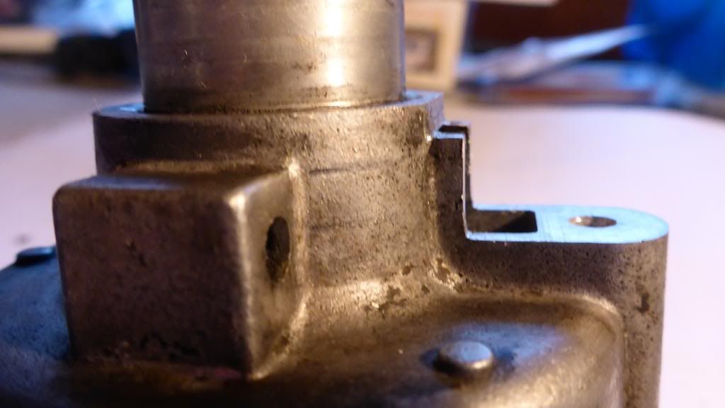
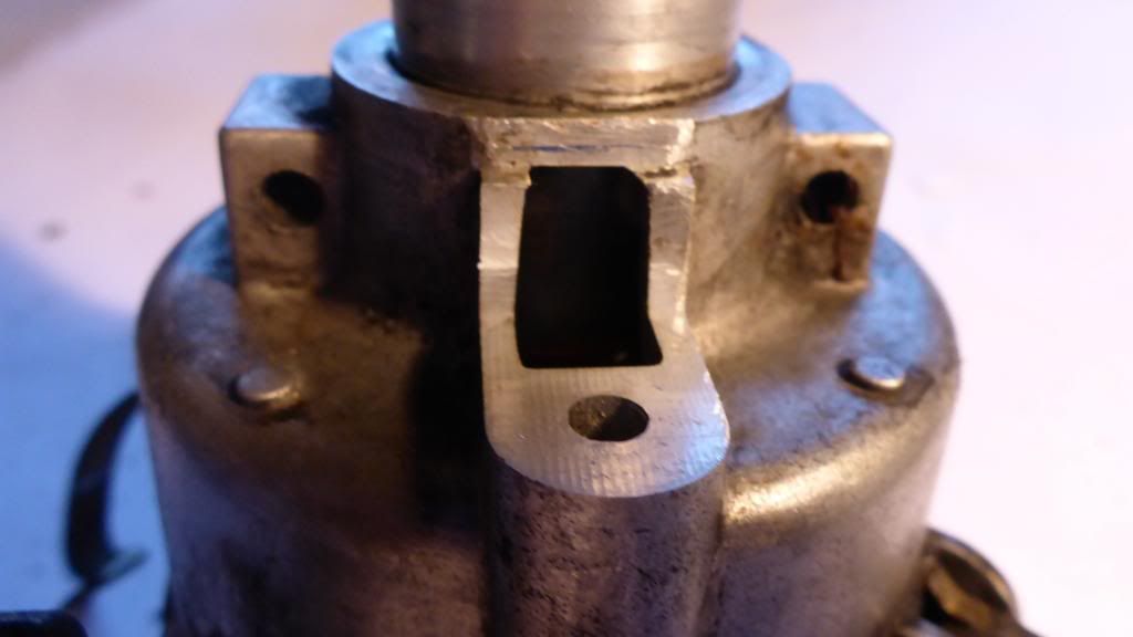
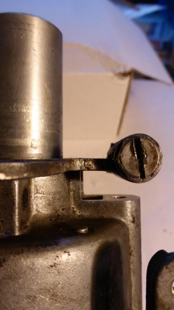
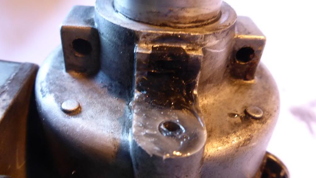

Here are some pictures of modifications I did to the donor distributor. The first 2 pictures show the area I milled off. The 1st small step is for the larger diameter E1 mounting plate to clamp on to. The larger part that is is milled of is clearance for the mounting plate's clamping bolt. The 3rd pic shows it with the mounting plate in place. I think filled the hole I created while milling that clearance with RTV (4th picture). Last picture is just of my truck after getting a cheap paint job


Re: Need help with EI distributor conversion... Please?
Well, I tossed the distributor in, adjusted it by eye to where timing was approx right and even though it has a little bit of a vacuum leak because there is no advance line the truck started right up. Unfortunately I don't seem to be able to get enough adjustment on the distributor to get the timing right before the vacuum advance unit hits the oil filter. It sounds ok but it is running way advanced. I'm going to have to pull it apart, rotate the distributor to new position and try again tomorrow.
Find Your Forum!