UPDATE - 02-12-11 - Master Cylinder Replacement
master-cylinder-replacement-t523910.html
UPDATE - 11/10/10 - Front sway bar end link bushing replacements
With all the repairs and mods I'm doing, gonna start my own page.
The PROPER HID conversion
This mod abandons your stock wiring as the wiring is too small to handle the load of HIDs. This will cause HID ballast failure and overheating of an already 20+ year old wiring system.
headlight-conversion-t471548.html
Instrument Cluster Clean
instrument-cluster-dissasembly-and-clean-t487096.html
Master Cylinder Replacement
master-cylinder-replacement-t523910.html
04/24/10 - Just did the compression/torsion rod bushings
Simple enough to do, needs a little elbow grease to but the bolts back in though.
5/6/10 - Coolant system overhaul
Prepare to get messy! This replaces EVERYTHING in regards to cooling. Thermostat, water pump, ALL hoses, radiator(new or rotted), fan, & clamps
5/8/10 - Instrument Cluster upgrade.
Remove those old black gauges and replace with new white ones!
8/4/10 - Front Wheel Bearing Change
Unfortunately due to the nature of grease getting everywhere, and not photo assistant, no pictures were taken. However everything is pretty self-explanatory.
My 720 Build Page
-
PEZi

- Posts: 20441
- Joined: Thu Dec 11, 2008 8:21 am
- Car: Mitsubishi Lancer Evolution IX Mitsubishi Racing Edition
- Location: Pikes Peak, CO
- Contact:
Re: My 720 Build Page
good stuff man! don't forget to keep everything up to date with pics!
Re: My 720 Build Page
Compression Rod bushings - Got mine from Autozone, not really all that expensive.
Tools:
15/16" open end wrench
11 mm socket
14mm socket
Elbow Grease
As you can see they are in dire need of replacement:

New and old bushings, I like that they are blue. The old ones kind of fell apart. There is a metal sleeve that comes with the new bushings, so all you need to do is remove the old ones and sleeve and toss them. Clean up the large washers and re-use. Since the new bushings are larger than the existing ones, due to the fact that they are new and not compressed from years of use, you will need some elbow grease to bolt the rod back in place.

New ones in place. Besides giving the truck an extra 50HP, the make the front end a little bit more smoother... Also note the length of the compression rod and how much doesn't stick out from the nut compared to the first picture. Haynes manual directs you to tighten the nut on than lower the car back onto the ground and tighten from there. Once on the ground, I could not get the nut to go on any further than shown.

Tools:
15/16" open end wrench
11 mm socket
14mm socket
Elbow Grease
As you can see they are in dire need of replacement:
New and old bushings, I like that they are blue. The old ones kind of fell apart. There is a metal sleeve that comes with the new bushings, so all you need to do is remove the old ones and sleeve and toss them. Clean up the large washers and re-use. Since the new bushings are larger than the existing ones, due to the fact that they are new and not compressed from years of use, you will need some elbow grease to bolt the rod back in place.
New ones in place. Besides giving the truck an extra 50HP, the make the front end a little bit more smoother... Also note the length of the compression rod and how much doesn't stick out from the nut compared to the first picture. Haynes manual directs you to tighten the nut on than lower the car back onto the ground and tighten from there. Once on the ground, I could not get the nut to go on any further than shown.
Re: My 720 Build Page
Coolant system overhaul!
Noticed I was leaking coolant from the bypass coolant hose going from the thermostat to the manifold underneath the carb.. From their the coolant goes to the heater core and than to the block. The coolant travels through the block to the water pump which in turn pumps it back through the system.
Tool/items needed:
standard screw driver
phillips head screw driver
12, 10, 8mm open end wrenches
upper / lower radiator hose
bypass hose
heater core inlet / outlet hose
hose clamps
3 gallons extended life coolant
thermostat with gasket
radiator cap
new or rotted radiator
water pump
rtv sealent
coolant reservoir hose
Drain radiator and dispose of coolant properly. There should be 9-10 quarts (2-1/4 - 2-1/2 gallons).
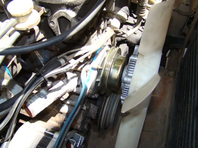
Remove upper radiator hose and the two thermostat housing bolts, remove thermostat and clean surfaces of all gasket remnants. Remove lower radiator hose. Picture shows lower radiator hose with upper hose and thermostat removed.
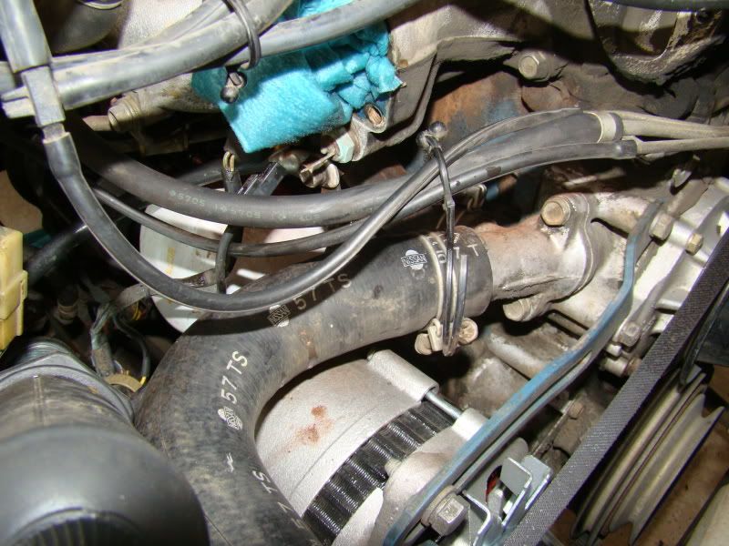
Lower hose removed. Clean surface of inlet.
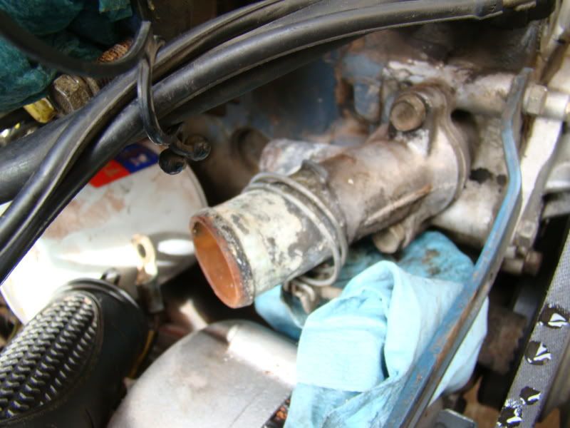
Remove radiator and fan shroud. Fan shroud has three phillips head screws, radiator has 4 bolts. Remove shroud first than push it up against the engine. Remove the lower radiator hose and slide up radiator. Remove shroud.
Water pump removal. Scrape surface clean of gasket remnants.
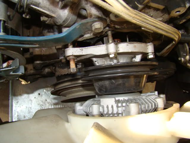
Water pump removed, judging by the impeller, this was a replacement.

New pump. This one directed extended life coolant be used. Note the impeller is cast iron.

Water pump removed. Note the orange-brownish sludge.

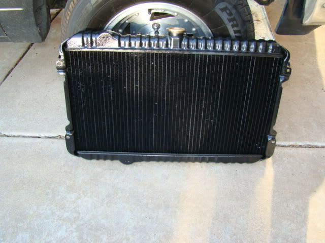
I opted to get my radiator rotted out rather than new. Cost 1/2 the price of new and is just as good. The person who did it said it was one of the worst he'd seen. Rotted just means the clean all the crap out of it, pressure and leak test it, paint it black and install a new petcock valve as well as neck extension for the reservoir tank.
You can see the engine inlet above the starter. This is where the new heater core hose attaches.

And with hose attached: above starter. I wasn't able to show the bypass hose connection because I couldn't get the camera under there. It is located directly underneath the carb. just trace the hose with your hand. You can see the outlet if you follow the fuel line from the fuel filter.

Water pump installed.
Do NOT tighten the lower radiator hose until after the radiator has been bolted onto the truck and the alternator has been set in place. My hose was touching the alternator pulley, and I had to go back and move the hose around a little. Tighten the lower radiator hose clamp before the fan shroud.

Double check all clamps and hoses for clearance.

Haynes calls for 9-10 quarts (4 quarts to the gallon = 2-1/4 - 2-1/2 gallons).

Pour 1 gallon into the radiator and let it settle for a few minutes. Fill the coolant reservoir tank to MAX. Start the truck and let it run until it gets hot. Make sure to watch the lower radiator hose for clearance. Shut truck off when it gets hot. Let it cool to 1/2 temp. and re-start. The lower radiator hose should compress as the water pump is creating vacuum trying to pull more coolant from the radiator. Turn truck off and you should hear sucking sounds from the coolant reservoir tank. The cooling is creating a vacuum from the tank to the radiator. When the tank is empty, refill to MAX and repeat the procedure until there are a minimum of 9 quarts of coolant installed. Verify with your year of truck.
Drive around for awhile, at least long enough to get the temp. at normal operating level. Park it and let it cool down. Re-tighten ALL the clamps to all the hoses at this point, especially the bypass hose underneath the carb. Use a 1/4" drive socket on the hose clamps to tighten them even further than allowed by the flathead.
Total overall cost:
$160.00
Noticed I was leaking coolant from the bypass coolant hose going from the thermostat to the manifold underneath the carb.. From their the coolant goes to the heater core and than to the block. The coolant travels through the block to the water pump which in turn pumps it back through the system.
Tool/items needed:
standard screw driver
phillips head screw driver
12, 10, 8mm open end wrenches
upper / lower radiator hose
bypass hose
heater core inlet / outlet hose
hose clamps
3 gallons extended life coolant
thermostat with gasket
radiator cap
new or rotted radiator
water pump
rtv sealent
coolant reservoir hose
Drain radiator and dispose of coolant properly. There should be 9-10 quarts (2-1/4 - 2-1/2 gallons).
Remove upper radiator hose and the two thermostat housing bolts, remove thermostat and clean surfaces of all gasket remnants. Remove lower radiator hose. Picture shows lower radiator hose with upper hose and thermostat removed.
Lower hose removed. Clean surface of inlet.
Remove radiator and fan shroud. Fan shroud has three phillips head screws, radiator has 4 bolts. Remove shroud first than push it up against the engine. Remove the lower radiator hose and slide up radiator. Remove shroud.
Water pump removal. Scrape surface clean of gasket remnants.
Water pump removed, judging by the impeller, this was a replacement.
New pump. This one directed extended life coolant be used. Note the impeller is cast iron.
Water pump removed. Note the orange-brownish sludge.
I opted to get my radiator rotted out rather than new. Cost 1/2 the price of new and is just as good. The person who did it said it was one of the worst he'd seen. Rotted just means the clean all the crap out of it, pressure and leak test it, paint it black and install a new petcock valve as well as neck extension for the reservoir tank.
You can see the engine inlet above the starter. This is where the new heater core hose attaches.
And with hose attached: above starter. I wasn't able to show the bypass hose connection because I couldn't get the camera under there. It is located directly underneath the carb. just trace the hose with your hand. You can see the outlet if you follow the fuel line from the fuel filter.
Water pump installed.
Do NOT tighten the lower radiator hose until after the radiator has been bolted onto the truck and the alternator has been set in place. My hose was touching the alternator pulley, and I had to go back and move the hose around a little. Tighten the lower radiator hose clamp before the fan shroud.
Double check all clamps and hoses for clearance.
Haynes calls for 9-10 quarts (4 quarts to the gallon = 2-1/4 - 2-1/2 gallons).
Pour 1 gallon into the radiator and let it settle for a few minutes. Fill the coolant reservoir tank to MAX. Start the truck and let it run until it gets hot. Make sure to watch the lower radiator hose for clearance. Shut truck off when it gets hot. Let it cool to 1/2 temp. and re-start. The lower radiator hose should compress as the water pump is creating vacuum trying to pull more coolant from the radiator. Turn truck off and you should hear sucking sounds from the coolant reservoir tank. The cooling is creating a vacuum from the tank to the radiator. When the tank is empty, refill to MAX and repeat the procedure until there are a minimum of 9 quarts of coolant installed. Verify with your year of truck.
Drive around for awhile, at least long enough to get the temp. at normal operating level. Park it and let it cool down. Re-tighten ALL the clamps to all the hoses at this point, especially the bypass hose underneath the carb. Use a 1/4" drive socket on the hose clamps to tighten them even further than allowed by the flathead.
Total overall cost:
$160.00
Last edited by 86 720 on Mon May 10, 2010 11:47 pm, edited 4 times in total.
-
breadbox

- Posts: 8549
- Joined: Tue Oct 17, 2006 4:09 pm
- Car: 89 Nissan 240SX
89 Koop
84 720 4x4KC - Location: Va Bch
Re: My 720 Build Page
Wow, Nice Write up. My Rad is pretty horrible, where do I take a rad to get rotted?
Re: My 720 Build Page
Most radiator shops do it. I found a few that wouldn't though. This is a double row radiator without plastic side pieces. For me it cost $65, which was less than half the cost of new from Autozone. Autozone wanted $142.00, taxes included.breadbox wrote:Wow, Nice Write up. My Rad is pretty horrible, where do I take a rad to get rotted?
Rotted just means the clean all the crap out of it, pressure and leak test it, paint it black and install a new petcock valve as well as neck extension for the reservoir tank.
Since I have installed it, it has not leaked on me and held up nicely.
-
PEZi
- Posts: 20441
- Joined: Thu Dec 11, 2008 8:21 am
- Car: Mitsubishi Lancer Evolution IX Mitsubishi Racing Edition
- Location: Pikes Peak, CO
- Contact:
Re: My 720 Build Page
looks decent man... but i won't lie... it looks like it could go tighter86 720 wrote:
Re: My 720 Build Page
It does, but they aren't going any further...PEZi720 wrote:looks decent man... but i won't lie... it looks like it could go tighter86 720 wrote:
Re: My 720 Build Page
Finally found my new cluster background.
Simply follow the instructions to remove the cluster and clean from my other link:
instrument-cluster-dissasembly-and-clean-t487096.html
When you get to the part about removing the faces, this is where you swap out the old and put in new. I found these whit gauge faces on ebay for about $15.00 shipped. Make sure to WASH your hands as the faces do transfer dirt quite easily. DO NOT follow the instructions that come with the gauges which directs you to lay the new face on top of the existing face. Remove the stock face, than remove the adhesive backing on the new face and place the new face on the cluster. Make sure to do this in an area where you can see the little mounting screws should they go flying.
New faces installed except for temp.. Be careful with the temp. and fuel needles, they bend easily.

Put back together. The only thing I don't like about this is that it changes the oil, battery, and seat belt light to orange, and the brights to green. I might re-install these back to stock. Since I don't have a trip odometer you can see through it at the speedometer mechanism. You'll need to cover it up with paper or something else. This is also a good time to upgrade the cluster lights to LEDs if you want.

Simply follow the instructions to remove the cluster and clean from my other link:
instrument-cluster-dissasembly-and-clean-t487096.html
When you get to the part about removing the faces, this is where you swap out the old and put in new. I found these whit gauge faces on ebay for about $15.00 shipped. Make sure to WASH your hands as the faces do transfer dirt quite easily. DO NOT follow the instructions that come with the gauges which directs you to lay the new face on top of the existing face. Remove the stock face, than remove the adhesive backing on the new face and place the new face on the cluster. Make sure to do this in an area where you can see the little mounting screws should they go flying.
New faces installed except for temp.. Be careful with the temp. and fuel needles, they bend easily.
Put back together. The only thing I don't like about this is that it changes the oil, battery, and seat belt light to orange, and the brights to green. I might re-install these back to stock. Since I don't have a trip odometer you can see through it at the speedometer mechanism. You'll need to cover it up with paper or something else. This is also a good time to upgrade the cluster lights to LEDs if you want.
-
PEZi
- Posts: 20441
- Joined: Thu Dec 11, 2008 8:21 am
- Car: Mitsubishi Lancer Evolution IX Mitsubishi Racing Edition
- Location: Pikes Peak, CO
- Contact:
Re: My 720 Build Page
well... the only problem, is if you take a look at the threads showing.... there's not as many showing as there should be... there's gotta be a way to make them tighter because they have more room to go.... when i put mine on, it was a pain to get them tight... but i did get them86 720 wrote:
It does, but they aren't going any further...
Re: My 720 Build Page
They're in as far as they will go.PEZi720 wrote:well... the only problem, is if you take a look at the threads showing.... there's not as many showing as there should be... there's gotta be a way to make them tighter because they have more room to go.... when i put mine on, it was a pain to get them tight... but i did get them86 720 wrote:
It does, but they aren't going any further...
-
Rev_D21

- Posts: 5946
- Joined: Sun Jan 12, 2003 9:49 pm
- Car: 1986.5 D21 LB HD 2WD V6 5Speed
1991 D21 Reg 2WD Auto
1995 D21 Reg 2WD 5Spd
1996 D21 Reg 4WD 5Spd
2012 Versa 1.6S 5-Speed - Location: Somwhere in Western NY
- Contact:
Re: My 720 Build Page
I noticed one of the washers is on backwards, may the the pic though. That may or may not have anything to do with your tightness problem. I replaced mine with the same Moog bushings but I was able to get them way more tight than that. Check your washers, they look backwards to me.
Re: My 720 Build Page
see above
-
PEZi
- Posts: 20441
- Joined: Thu Dec 11, 2008 8:21 am
- Car: Mitsubishi Lancer Evolution IX Mitsubishi Racing Edition
- Location: Pikes Peak, CO
- Contact:
Re: My 720 Build Page
are you using that open ended wrench on it? that may be the issue... i used a GIANT socket wrench for lots of torque. i promise you, they are meant to be tighter and i can get you a pic of mine if you'd like. but from the photo you took, your bushing isn't even compressed yet on the front side.... and it should be.
-
breadbox
- Posts: 8549
- Joined: Tue Oct 17, 2006 4:09 pm
- Car: 89 Nissan 240SX
89 Koop
84 720 4x4KC - Location: Va Bch
Re: My 720 Build Page
If it falls off while driving, You might have wished they were tighter. Any reason you feel they are "tight" enough?
-
flinterman2000
- Posts: 1011
- Joined: Mon May 04, 2009 5:32 pm
- Car: 2000 Nissan Wingroad, 85 Datsun 720 Pick Up.
Re: My 720 Build Page
Left side washer is on wrong. Use a breaker bar and the right socket (6 point) and it will tighten.
Re: My 720 Build Page
Front Bearing Replacement
Unfortunately no pictures were taken as this is a very messy job. However a search on youtube brings good results. This is also a good time to change the front brake shoes as you have to remove the caliper and caliper bracket.
Tools:
Lots of shop towels!
3/4" socket/wrench
6" ratchet extension
12mm socket/wrench
large flat blade screw driver
small flat blade screwdriver
phillips head screw driver
Wheel bearing grease - I used Valvoline Japanese high temp. grease
Inner & outer front bearings - Timkin - Set5 & Set3
Outer Seal - X2
1 full can of Brake cleaner
Anti-seize
Section of 2x4
Hammer or Rubber Mallet
2" diameter pipe - 6" or less - Home Depot - $2.33 for a 3" section
Small handheld wire brush
Cotter Pins
Medium Crescent wrench
Step 1
Check to see if you need to replace the bearings. Jack the car up and place the front end on jack stands. With the wheel on, grab it at the 12 & 6 o'clock positions and wriggle the wheel back and forth. If it doesn't move, the bearings are fine, if they do move, time to replace! However if one side needs to be replaced, than replace both sides, just like brake pads. Remove wheels and set aside along with lug nuts.
Step 2
Remove caliper using the 12mm socket/wrench. As always, use a strap or coat hangar to tie it up and prevent accidental breakage of the brake hose.
Step 3
Remove existing brake shoes.Remove caliper mounting bracket using the 3/4" socket/wrench. Clean all mating surface, set aside.
Step 4
Clean the mating face of hub using the wire brush and brake cleaner. Using the small screw driver, pry off the dust cap and clean all the grease out of it. Clean grease from the retaining nut area. Remove cotter pin and toss, remove retainer cover, spindle nut,and spindle washer. Clean all these pieces and set aside. At this point the existing front bearing should just fall out.
Step 5
With a clean set of hands or gloves, grab the entire hub/rotor assembly and pull it off the spindle. Wipe off ALL grease and clean spindle off. Optional to clean off the backing plate as well. Tighten the 4 phillips head screws holding the backing plate attached. Mine were all somewhat loose on both sides.
Step 6
Optional Part: Separate hub from rotor. I didn't do this, but you can if you want.
Step 7
Clean out ALL the grease from the interior of the hub, being careful not to get any on the rotor surface. There is a LOT of grease in that hub, but make sure to get it all out and as clean as possible. I had to remove the bearing and the raceways before I could get it all out of the interior.
Step 8 - Outer Bearing removal
Optional Part: Some people don't remove the raceway and leave it in place. This is ok as long as the inner race is clean and free from any chips, cracks or defects. The new bearing comes with a new race, it is the removable outer ring that comes off the conical shaped bearing.
Starting with the smaller outer bearing, use the small screw driver. Flip the rotor/hub assembly on it's face(studs facing the ground) and insert the screwdriver inside the hub and on the lip of the race. You will notice, once all the grease is removed, there is a section of the inner hub that is cut away that allows access to a larger section of the race. One can use the large screwdriver or the ratchet extension, I used both. Using the large screw driver, place the tip of the screw driver on this surface and give it a good whack with the mallet or hammer. If you leave the rotor attached, make sure you don't hit the surface and accidentally mar the surface. You will need to do this several times at different parts of the race to push it out. You can also use an air drill with a flat face bit. Take note of how the race is facing for re-installation. In other words, the narrow conical face of the race should be facing the center of the hub. A good way to determine this is by installing the old bearing and seeing how it fits, the new bearing will install the same way.
Step 9 - Inner Bearing and Seal removal
Same procedure as above, however you will see that the seal inserts INTO the hub. At first I was fooled and thought the seal was fitted over the hub as there is a lip around the edge of the hub. That lip is NOT the seal. The inner race is installed, than the bearing followed by the seal. You will see that the inner bearing itself can't be removed without removing the seal first, but the seal itself doesn't have a strong enough lip to mount the screwdriver to and hammer it out, so the inner race HAS to be removed. Another problem is that the edge of the seal is at the same height of the rotor if it is still installed. You'll know what I mean when you get this far. Removal of the inner race is the same as above. Flip the rotor/hub on it's back over two pieces of wood so that the center of the hub is free from obstruction. Make sure the surface of the rotor is protected. Hammer the race, bearing and seal out
Step 10
THOROUGHLY CLEAN out the interior of the rotor/hub, again there is a LOT of grease in there! Using new grease, repack the interior of the rotor/hub. Apply a thin coat of grease to the mating surface of the bearing races that were removed. This will allow the new races to be installed a little bit easier.
Step 11
Pack the bearings with grease and put a lite coat of grease on the races as well. Set the bearings aside and install the races first.
MAKE SURE YOU KNOW IN WHICH DIRECTION THE RACES ARE INSTALLED! The last thing you need is to find you installed the races the wrong directions and the bearing won't fit. You'll know immediately when you try to install the bearing. You'll have to hammer out the race again and re-install it.
Step 12
Starting with the smaller outer bearing, flip the rotor/hub assembly on its back, studs facing ceiling, and place the greased race on the hub. You really won't be able to push it in with your hands, but try to center it as much as possible. Make sure the surface of the rotor is protected by using a thick stack of newspaper or some other item. Take the block of wood and with the hammer or mallet, push the race in until you can't hammer it in any further. Again, make sure you protect the race and bearing by using paper or something else in between them and the block of wood. You will see that once you place the bearing inside, it is not quite flush with the edge of the hub. Leave the bearing there and hammer it the rest of the way with the block of wood and hammer/mallet. There is NO seal to install on this side, so the bearing will fall out if you flip it over. Set the greased bearing aside until you re-install the entire rotor/hub assembly onto the spindle.
Step 13
Installation of the larger inner bearing is done the same way, except once you installed the race and the bearing, you place the seal on top of those and hammer that in as well. Again, make sure you grease the race and also grease the seal as well. With the seal installed, it should be flush withe the edge of the hub.
Step 14
Apply new grease onto the cleaned spindle. Not a large amount, but enough to adequately cover the surface of the spindle. Re-install the rotor/hub assembly with the new bearings and seal onto the spindle and push it all the way onto the spindle. Install the outer bearing, the rotor/hub assembly will center itself onto the spindle at this point. If the bearing won't fit on the spindle, you either installed the race incorrectly or you have to wiggle the rotor/hub assembly to center it.
Step 15
Apply a lite coat of grease to the spindle washer and nut. Prior to installing the spindle cover and cotter pin, tighting the nut as tight as you can than loosen it 1/4 turn with the crescent wrench. Spin the rotor and tighten the nut again until the rotor stops spinning. Loosen 1/4 turn again and repeat the procedure several times. You're seating the bearings at this point. On the last time, tighten than loosen 1/4 turn and install the cover and cotter pin making sure to bend the edges of the cotter pin to prevent it from wriggling out. Add a dollop of new grease to the dust cap and re-install using the 2" diameter piece of pipe.
Step 16
Thoroughly clean the rotor surface making sure all grease and other foreign matter is clear. Re-attach the caliper mounting bracket, replace brake shoes at this point, and attach caliper.
Step 17
Attach wheel. At this point, if you installed the bearings right, grab the wheel at the 12 & 6 o'clock position and wriggle the wheel. It should NOT wriggle if you have installed the bearings correctly. Repeat for other side.
-
synack7350
- Posts: 364
- Joined: Sun Jan 09, 2011 3:08 pm
- Car: nissan '83 720 king cab pickup 2wd 2.4L Z24
- Location: Boaz, AL
Re: My 720 Build Page
yeah strut rod bushings were a bear. I'm 180 pound fit ex-soldier using a 1/2" drive breaker bar. I got so wore out I dug up a cheater bar to finish them up. the trick is to remove the two bolts that mount the strut rod to the a arm and ball joint. put your ends on and crank and crank and crank till the holes get close enough to lining up to get the bolts in. That's about the neighbor hood of tightness you want on those bushings. other wise under braking you'll have play in your front end. my chariot stops on a dime on stock brakes perfectly even no pull this away or that away.
-
Bloodman324
- Posts: 112
- Joined: Sun Jul 03, 2011 9:02 pm
- Car: 1981 Datsun 720 Kingcab 2WD Automatic
Re: My 720 Build Page
Damn!! them gauge faces look sharp! makes me want to do something with my gauge faces and the background light lol change it from that green to maybe a nice blue light or somethin haha were did you find the different color gauge faces at?
-
synack7350
- Posts: 364
- Joined: Sun Jan 09, 2011 3:08 pm
- Car: nissan '83 720 king cab pickup 2wd 2.4L Z24
- Location: Boaz, AL
Re: My 720 Build Page
I ordered mine from ebay. they are white with blue shine through. http://cgi.ebay.com/ebaymotors/_W0QQcmd ... MEWNXQ3aIT
this fellar might have them for the square faced gauges too I dunno. if you search prior to 83 you should find some.
this fellar might have them for the square faced gauges too I dunno. if you search prior to 83 you should find some.
-
Bloodman324
- Posts: 112
- Joined: Sun Jul 03, 2011 9:02 pm
- Car: 1981 Datsun 720 Kingcab 2WD Automatic
Re: My 720 Build Page
Sweeeet! haha thanks, i hope they do have them for the square gauges cuz that would be awesome!
-
pistolkeith
- Posts: 50
- Joined: Sun Sep 18, 2011 11:36 pm
- Car: 1985 Nissan King Cab 720
Re: My 720 Build Page
I am a new kid to the Nissan 720 club. I know a little about cars, but all this DIY stuff kinda freaks me out. Does anyone know anyone trustworthy(aka not Firestone) that local to the Los Angeles area who can help me out with suspension bushing and compression rod bushing replacement like above?? i just dont want to get screwed by some dirty mechanic who charges me his labour including his time to go get a burger for lunch!