
KP Technologies Fog Light Controller
-
jiggersplat
- Posts: 352
- Joined: Mon Mar 17, 2014 3:21 pm
- Car: 2008 Infiniti M45x
1995 Toyota Supra TT 6-spd - Location: Alexandria, VA
KP Technologies Fog Light Controller
Installing mine now... not quite working right. Anyone else installed one yet?
-
fat3oy
- Posts: 305
- Joined: Wed Aug 31, 2011 1:09 am
- Car: 07 M35X, 06 350z, 06 RSX, 99 Dajiban
- Location: Charlotte, NC
Re: KP Technologies Fog Light Controller
I've installed a ton of KP modules over the years... not this particular one - but it is a legit company, and products work
Re: KP Technologies Fog Light Controller
fat3oy wrote:I've installed a ton of KP modules over the years... not this particular one - but it is a legit company, and products work
Question Sir. Have you installed the auto door lock module or the "OK" navigation button bypass module from KP on a m45? Looking for a little help on installing these, Thanks.
-
jiggersplat
- Posts: 352
- Joined: Mon Mar 17, 2014 3:21 pm
- Car: 2008 Infiniti M45x
1995 Toyota Supra TT 6-spd - Location: Alexandria, VA
Re: KP Technologies Fog Light Controller
Okay.... here's the relevant wiring diagrams for my 2008 M45x. I'd guess that they are the same at least for the 08-10 models, but everyone should check their specific year before attempting this. The relevant sections of the FSM are BCS.pdf and LT.pdf
First let's install the KP tech module at the BCM.
Here is the combination switch matrix. You can see that the fog lights are controlled by Output 5 and Input 4
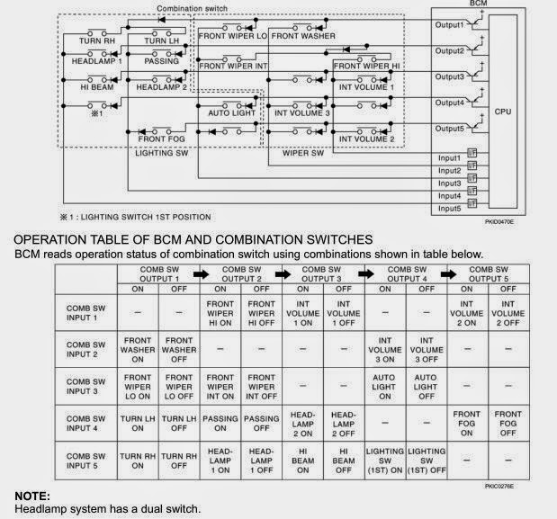
Output 5 is pin 32 on the BCM and is Light Green.
Input 4 is pin 3 on the BCM and is Orange with a bLue stripe.

- Remove your glovebox. Unsnap the string on the right hand side and wiggle it out.
- Remove the plastic panel underneath. Give the front edge a tug downward
- Remove the access panel to the cabin air filter
- Remove about 9 screws holding in the panel covering all the electronics. You may need to remove the panel on the right hand side near the door hinge. Just give it a tug.

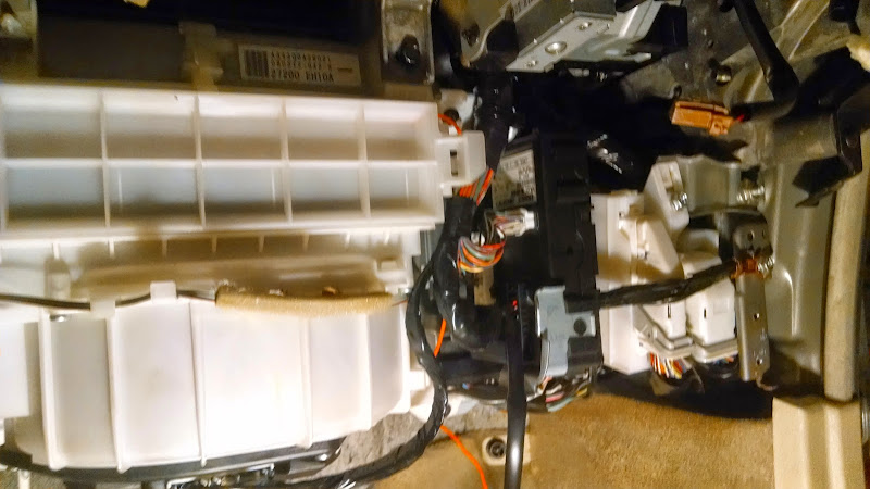
The BCM is towards the right mounted vertically on a metal bracket. It probably has a sticker on it that says Calsonic. The connector you want is the white horizontal one just under the sticker.
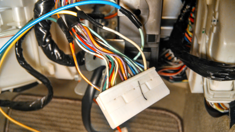
This is where you'll need to splice a few wires.
- 12v switched BCM pin 40 White to KP Yellow
- Output 5 BCM pin 32 Light Green to KP Blue
- Input 4 BCM pin 3 Orange bLue to LP Green
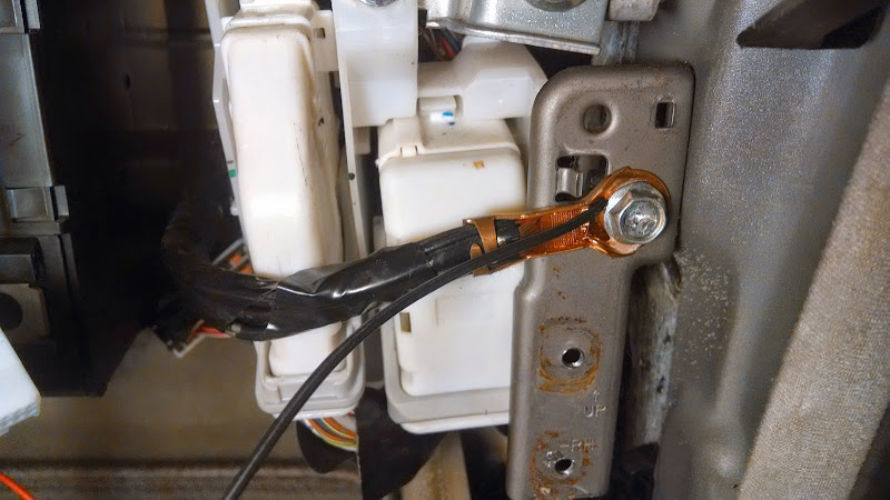
I connected the ground (KP Black) here
- Run KP Orange through the firewall. I just cut a small notch in the air filter housing and ran mine through there.
- Test the KP module before going any further. You should see a red LED light up right next to the connector when the fog light switch is in the on position and the ignition is ON. If your LED doesn't come on, double check everything.
Now for the under-hood stuff.
- Remove the passenger side engine cover, battery cover, battery cover holder
- Remove the passenger side cowl by pulling back the gasket. There is a clip right in the center of the cowl. Pull the tab up and slide the cowl forward and down.
- Remove the battery
- Locate the IPDM against the firewall near the hood hinge and remove the cover
- Remove the large relay in the center for easier access to the connector we want (it's the one just below the relay)
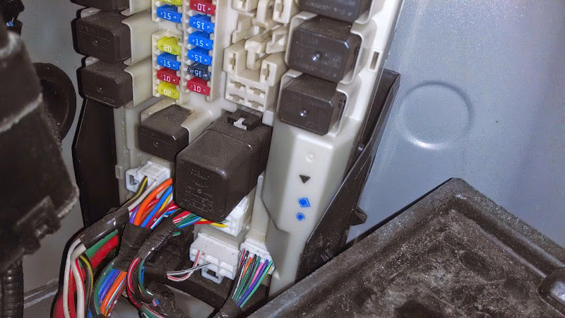
- The left fog light is bLue with a Yellow stripe
- The right fog light is White with a Red stripe

- You'll need to cut the two wires for the fog lights. The are right next to each other. Make sure you cut them far enough from the connector that you are able to work with them. It's the top left two in the photo below.
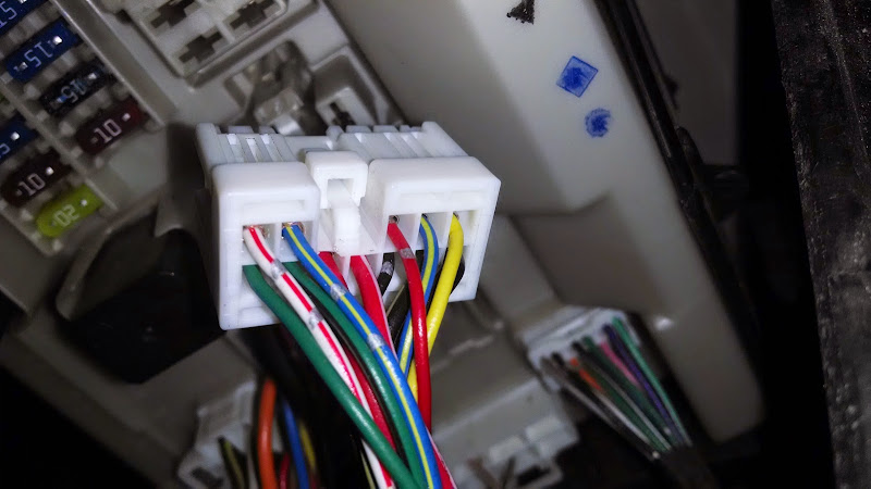
This is where things get screwy... the directions that come with the KP tech module, the colors it refers to for the relay socket weren't correct for mine so be careful here.
- Splice both wires that you just cut running to the foglights to pin 30 on the relay. The wire for mine happened to be black.
- Connect either of the wires you cut coming from the IPDM to pin 87A on the relay. Mine was blue.
- Termite the other wire from the IPDM (electrical tape or otherwise)
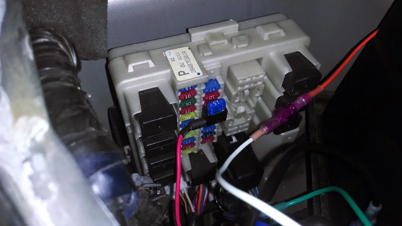
- Connect the orange wire running through the firewall to ping 85 on the relay. Mine was white.
The last two wires on the relay, 86 and 87 (red and green respectively on mine) get connected to high current switched power. I decided to use an add-a-fuse device and this is where things went horribly wrong in my install. Don't do what I did. It makes a difference what direction you install it. Also, don't install it on the ABS circuit cause if you blow that fuse your car goes bonkers. I ended up installing it on the washer pump fuse.
- At this point I would test the relay. Disconnect the KP tech module from it's harness. Your fog lights should work just like they did before you installed anything. If they don't turn on, you screwed up the relay installation.
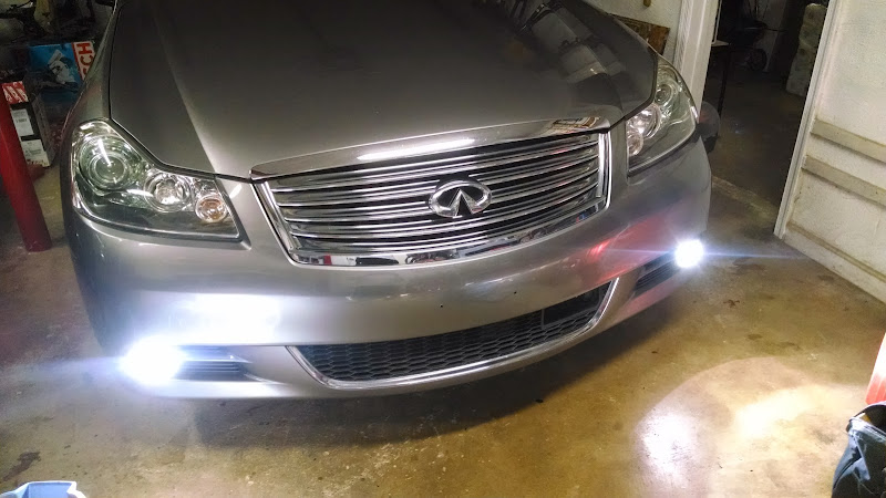
- If that's working, plug the KP tech module back into it's harness. You should be all set at this point. Secure the KP tech module behind the glovebox somewhere. I double-sided-taped mine to the back of the BCM. Secure the relay under the hood. I ziptied mine to one of the harnesses next to the battery. Button everything back up and enjoy.
Here's a summary of the wiring.... as always mileage may vary.

Download spreadsheet here https://docs.google.com/spreadsheets/d/ ... ingle=true
First let's install the KP tech module at the BCM.
Here is the combination switch matrix. You can see that the fog lights are controlled by Output 5 and Input 4
Output 5 is pin 32 on the BCM and is Light Green.
Input 4 is pin 3 on the BCM and is Orange with a bLue stripe.
- Remove your glovebox. Unsnap the string on the right hand side and wiggle it out.
- Remove the plastic panel underneath. Give the front edge a tug downward
- Remove the access panel to the cabin air filter
- Remove about 9 screws holding in the panel covering all the electronics. You may need to remove the panel on the right hand side near the door hinge. Just give it a tug.
The BCM is towards the right mounted vertically on a metal bracket. It probably has a sticker on it that says Calsonic. The connector you want is the white horizontal one just under the sticker.
This is where you'll need to splice a few wires.
- 12v switched BCM pin 40 White to KP Yellow
- Output 5 BCM pin 32 Light Green to KP Blue
- Input 4 BCM pin 3 Orange bLue to LP Green
I connected the ground (KP Black) here
- Run KP Orange through the firewall. I just cut a small notch in the air filter housing and ran mine through there.
- Test the KP module before going any further. You should see a red LED light up right next to the connector when the fog light switch is in the on position and the ignition is ON. If your LED doesn't come on, double check everything.
Now for the under-hood stuff.
- Remove the passenger side engine cover, battery cover, battery cover holder
- Remove the passenger side cowl by pulling back the gasket. There is a clip right in the center of the cowl. Pull the tab up and slide the cowl forward and down.
- Remove the battery
- Locate the IPDM against the firewall near the hood hinge and remove the cover
- Remove the large relay in the center for easier access to the connector we want (it's the one just below the relay)
- The left fog light is bLue with a Yellow stripe
- The right fog light is White with a Red stripe
- You'll need to cut the two wires for the fog lights. The are right next to each other. Make sure you cut them far enough from the connector that you are able to work with them. It's the top left two in the photo below.
This is where things get screwy... the directions that come with the KP tech module, the colors it refers to for the relay socket weren't correct for mine so be careful here.
- Splice both wires that you just cut running to the foglights to pin 30 on the relay. The wire for mine happened to be black.
- Connect either of the wires you cut coming from the IPDM to pin 87A on the relay. Mine was blue.
- Termite the other wire from the IPDM (electrical tape or otherwise)
- Connect the orange wire running through the firewall to ping 85 on the relay. Mine was white.
The last two wires on the relay, 86 and 87 (red and green respectively on mine) get connected to high current switched power. I decided to use an add-a-fuse device and this is where things went horribly wrong in my install. Don't do what I did. It makes a difference what direction you install it. Also, don't install it on the ABS circuit cause if you blow that fuse your car goes bonkers. I ended up installing it on the washer pump fuse.
- At this point I would test the relay. Disconnect the KP tech module from it's harness. Your fog lights should work just like they did before you installed anything. If they don't turn on, you screwed up the relay installation.
- If that's working, plug the KP tech module back into it's harness. You should be all set at this point. Secure the KP tech module behind the glovebox somewhere. I double-sided-taped mine to the back of the BCM. Secure the relay under the hood. I ziptied mine to one of the harnesses next to the battery. Button everything back up and enjoy.
Here's a summary of the wiring.... as always mileage may vary.
Download spreadsheet here https://docs.google.com/spreadsheets/d/ ... ingle=true
-
Ilya

- Moderator
- Posts: 9803
- Joined: Fri Apr 23, 2010 11:20 pm
- Car: 2011 M56x but I spend a lot of time on my 2015 Kawasaki Vulcan S. Former owner of a 2007 M35x. Also take care of my wife's 2016 QX60.
- Location: Charlotte, NC
- Contact:
Re: KP Technologies Fog Light Controller
BOOMSHAKALAKA. This is getting added to the FAQ. Good work, sir.
Re: KP Technologies Fog Light Controller
Just curious, I could have sworn I saw this somewhere here before, isn't there a way to do this without the module? Only reason I ask is because if this much splicing has to be done with the module anyway, why not just go commando style and do it without the module...if it's possible. I would think a "module" should come with necessary harnesses to be plug and play.
-
jiggersplat
- Posts: 352
- Joined: Mon Mar 17, 2014 3:21 pm
- Car: 2008 Infiniti M45x
1995 Toyota Supra TT 6-spd - Location: Alexandria, VA
Re: KP Technologies Fog Light Controller
There is a way to do it without the modules. You still have to cut wires though. You'd be cutting the wires at the control stalk instead of just tapping @ the BCM and you'd still need to install a relay and cut the wires at the IPDM. So not a ton of benefit.TDot wrote:Just curious, I could have sworn I saw this somewhere here before, isn't there a way to do this without the module? Only reason I ask is because if this much splicing has to be done with the module anyway, why not just go commando style and do it without the module...if it's possible. I would think a "module" should come with necessary harnesses to be plug and play.
Re: KP Technologies Fog Light Controller
But that's my thing, I pay for this when you have to splice and tap wires regardless? Relays are $3-$10. Is it a matter of avoiding splicing at the stalk? Is that more troublesome?
-
jiggersplat
- Posts: 352
- Joined: Mon Mar 17, 2014 3:21 pm
- Car: 2008 Infiniti M45x
1995 Toyota Supra TT 6-spd - Location: Alexandria, VA
Re: KP Technologies Fog Light Controller
It's more work to do it at the stalk but I wouldn't say it's significant. You'd have to run the wire from the stalk to the IPDM which is a little harder now because you've got to go from the driver's side to the passenger side. I guess it's mostly personal preference. If they had built the relay into the module, then I'd say definitely worth it, but you're right. You can do it without the module and it's not all that much harder.
Find Your Forum!