
how to: fix s13 wiring for gauge cluster/custom gauges
-
compactfean
- Posts: 2602
- Joined: Thu Dec 03, 2009 10:28 am
- Car: 89 240sx s13 sr gt3071r 23psi
B14 sentra ser sr20de-t 7psi
daily - Location: reno nv
how to: fix s13 wiring for gauge cluster/custom gauges
hello all! so ive been on here for a while and given good advice and received a lot of help from all of you and now its my turn to give back to the community! i've seen a ton of posts lately about gauges and wiring lately so here it goes. i will give as much info about the gauge cluster that i know and tips and tricks to wire custom gauges in the stock cluster. i will not be responsible for you any of your mistakes in this thread.
-
compactfean
- Posts: 2602
- Joined: Thu Dec 03, 2009 10:28 am
- Car: 89 240sx s13 sr gt3071r 23psi
B14 sentra ser sr20de-t 7psi
daily - Location: reno nv

-
compactfean
- Posts: 2602
- Joined: Thu Dec 03, 2009 10:28 am
- Car: 89 240sx s13 sr gt3071r 23psi
B14 sentra ser sr20de-t 7psi
daily - Location: reno nv
Re: how to: fix s13 wiring for gauge cluster/custom gauges
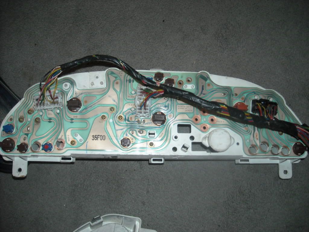
ok, first of all i will start with how the circuitry works and how you can fallow this maze ...simple. everywhere that you see the brown squiggles in the sheet attached to the back of the cluster? imagine those as just regular wire. notice how you can fallow from where the plug goes into to all over the board? this is why i have sharpie all over it so i could trace were voltage was going.
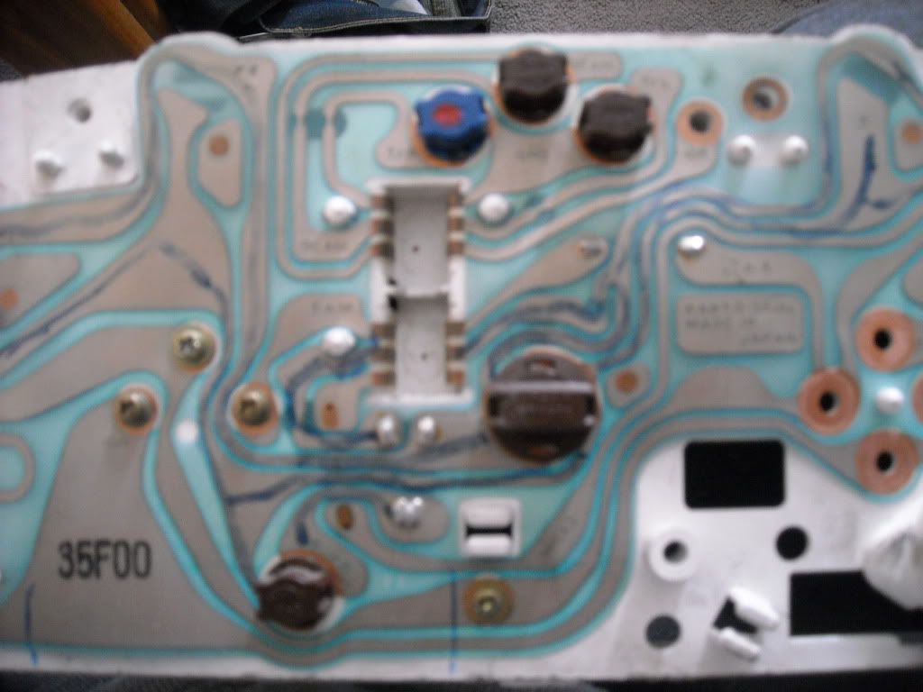
next is how do each individual gauges work? simple, and with how they work is how you can put in any gauges you want!!! so you see how if you where to take the cluster apart there are 4 main gauges tach, temp, speed, fuel. all of these gauges are bolted in with 3 screws (except speedo which is 4 screws). These screws are key to your gauges working! notice how there is copper where the screw goes into. those are power supply, ground, and signal. at the very bottom of the cluster where there are two bolts far appart are for the clock power and ground.
with this being said how do i figure out what these abbreviations are? lets start.
chg- charging system, notice how ign powers the bulb and then after the bulb goes back to the harness to make the dummy light work ( otherwise the dummy light would be on all the time)
door- pretty simple, notice how ign also goes to bulb and then underneath there is a soldered jumper and then goes to harness to make it work. this is simple because if there is a door open all its doing is grounding that bulb. if light doesnt go out replace door sensors.
gnd- this is the gound circuit for everything and there are multiple points where it says gnd main thing to check for here is if there is 12v on the ground wire. big nono.
tm- temp signal for gauge. if temp gauge has power and ground and still doesnt work then take a jumper wire and ground out the "tm". if the gauge maxes out then the gauge does work
ign- the most important, 12v with key on. also probably the most common problem
brk- there are two brk's one for brake and one for seatbelt, again, ign powers the bulb and works by going back to the harness
batt- 12v constant power to the clock
beam, t/r, t/l, gnd and the other beam are all part of the blinkers and highbeams. only problem i ever see with these are bulbs. i will explain further at request
tam- tach signal input from ecu.
ill+ illumination for gauge cluster lights.
fuel- is the fuel gauge ground
fm- is the signal from sending unit in the tank, ground fm and the gauge should max out.
-
compactfean
- Posts: 2602
- Joined: Thu Dec 03, 2009 10:28 am
- Car: 89 240sx s13 sr gt3071r 23psi
B14 sentra ser sr20de-t 7psi
daily - Location: reno nv
Re: how to: fix s13 wiring for gauge cluster/custom gauges
i will post all of the wire colors and description in a bit.
-
compactfean
- Posts: 2602
- Joined: Thu Dec 03, 2009 10:28 am
- Car: 89 240sx s13 sr gt3071r 23psi
B14 sentra ser sr20de-t 7psi
daily - Location: reno nv
Re: how to: fix s13 wiring for gauge cluster/custom gauges
ok so looking at the cluster like in the pictures ill start with the left plug.
red/black stripe- 12v constant power to the clock
black- one of the cluster common grounds
blue/black stripe- signal for temp gauge. ground this to chassis to test of gauge is working. The temp will max out if working properly
white/red stripe- alternator voltage dummy light
green- 12v ignition switched. this is what powers everything, bulbs gauges, everything.
yellow green stripe- for this plug only (there are multiple yellow/green wires on the cluster). seat belt dummy light trigger. not needed
yellow/white stipe-oil pressure dummy light trigger
yellow/purple- brake dummy light. rather low brake fluid or e-brake on. not needed in my case.
middle plug
green/yellow stripe- power to right turn signal dummy light when blinking
red/green stripe-high beam dummy light (power or ground, havent tested which one)
pink/black stripe- high beam dummy light (rather power or ground, whatever the red green isnt)
yellow/red stripe- tach signal from ecu. tach signal input for gauge
blue- 12v power for backlights when headlights are on
red/blue stripe- right side of cluster 12v power for backlights with headlights on.
yellow/black stripe- common ground for some gauges and lights
green/black stripe- unknown, doesnt go to anything on base model cluster. not needed (not sure about digital, but it goes go to an empty spot on mine that says 10k)
black- common ground for headlight and high beam dummy lights
third plug
red- unknown, not needed for base model but goes to "alb" so maybe the dummy light on abs cars?
black- ground for 2nd from right dummy light if you were to look at it from the front. ties into the ground for headlight dummies on middle plug deaper in the harness. not needed.
green/white stripe-2nd from right dummy light signal. not needed/unknown.
blue/maroon stripe- middle dummy light signal. unknown/not needed
red/blue stripe- low washer fluid dummy light. if you have jdm cluster the gauge will be the exhaust temp dummy light but when your low on washer fluid it will still light up. not needed in my case
yellow green- there are 2 yellow green wires on this plug. both go to speedo, one goes to a spot written in Japanese. the other goes to a spot that says 2p. i think the "2p" is the signal but not sure....need to do some research on this one.
red/orange stripe- backlight ground wire. this was a problem for me because i was getting 12v here and caused my fuses to keep popping and bulbs to get burnt
green/blue stripe-fuel sending unit signal. ground this wire to test if fuel gauge is working. it should max out the gauge just like the coolant temp gauge.
red/black stripe- low fuel dummy light signal/ dont think you need this wire for fuel gauge to work but havent tested this.
-
compactfean
- Posts: 2602
- Joined: Thu Dec 03, 2009 10:28 am
- Car: 89 240sx s13 sr gt3071r 23psi
B14 sentra ser sr20de-t 7psi
daily - Location: reno nv
Re: how to: fix s13 wiring for gauge cluster/custom gauges
so for custom gauges the best way to do this is to remove the gauge being replaced (whatever bolts are holding it in) and put the bolts back in with a nut on the inside of the cluster. fallow from where the wire goes for power, ground and signal and label that bolt for what it is. now solder the wires from your new gauge to whichever bolt needed (power ground,whatever) and then fabricate the bracket for the new gauge so it sits flush with the front plastic cover. the front housing will have to be modified with a new piece that cleanly gives each gauge a "boarder" like the stock gauges have. i wish i had pics of the custom pivot gauge cluster that i did to show how sic a stock cluster can look.
Any questions? i can edit the pics i have up there to point out specifics and re post if more detail is needed.
Any questions? i can edit the pics i have up there to point out specifics and re post if more detail is needed.
-
compactfean
- Posts: 2602
- Joined: Thu Dec 03, 2009 10:28 am
- Car: 89 240sx s13 sr gt3071r 23psi
B14 sentra ser sr20de-t 7psi
daily - Location: reno nv
Re: how to: fix s13 wiring for gauge cluster/custom gauges
Oh one more thing. After market gauges usually have there own illumination wire so what. You can do there is drill a hole in the side or bottom and run that wire out of the cluster and splice it into the blue wire, middle plug. That way your not drilling a hole through the circuit sheet.
-
OutToWinPAHC

- Posts: 9437
- Joined: Thu May 31, 2007 12:19 pm
- Car: 2015 Silverado, R33 GTST, R32 GTR, RB20 E46 RHD, 2015 Harley Vrod Muscle, 1990 Nissan Patrol
- Location: PA
- Contact:
Re: how to: fix s13 wiring for gauge cluster/custom gauges
Did this years back, thanks for posting.
-
compactfean
- Posts: 2602
- Joined: Thu Dec 03, 2009 10:28 am
- Car: 89 240sx s13 sr gt3071r 23psi
B14 sentra ser sr20de-t 7psi
daily - Location: reno nv
Re: how to: fix s13 wiring for gauge cluster/custom gauges
Thanks man. I searched and couldn't find anything on here and there's been alot of posts regarding this stuff. Hey do you remember the two speedo wires which one is signal? Does the 2p go to ecu? If you don't remember its ok ill find it in the fsm.OutToWinPAHC wrote:Did this years back, thanks for posting.
-
OutToWinPAHC
- Posts: 9437
- Joined: Thu May 31, 2007 12:19 pm
- Car: 2015 Silverado, R33 GTST, R32 GTR, RB20 E46 RHD, 2015 Harley Vrod Muscle, 1990 Nissan Patrol
- Location: PA
- Contact:
Re: how to: fix s13 wiring for gauge cluster/custom gauges
Its in the FSM el section I dont use a Nissan VSS but I needed indicators so I just used the FSM
-
compactfean
- Posts: 2602
- Joined: Thu Dec 03, 2009 10:28 am
- Car: 89 240sx s13 sr gt3071r 23psi
B14 sentra ser sr20de-t 7psi
daily - Location: reno nv
Re: how to: fix s13 wiring for gauge cluster/custom gauges
So I did my homework and the yellow blue wire that goes to the PCB with Chinese writing. Is the signal from the vSS. The yellow /green wire that goes to 2p is the signal that has been converted and goes to ecu.
Last edited by compactfean on Thu Mar 10, 2011 4:25 pm, edited 1 time in total.
Re: how to: fix s13 wiring for gauge cluster/custom gauges
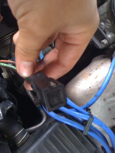
The yellow/red wire from the tam leads all the way to this square module. You think the module is fried?
-
compactfean
- Posts: 2602
- Joined: Thu Dec 03, 2009 10:28 am
- Car: 89 240sx s13 sr gt3071r 23psi
B14 sentra ser sr20de-t 7psi
daily - Location: reno nv
Re: how to: fix s13 wiring for gauge cluster/custom gauges
Rather you fallowed the wrong wire or you have a very simple fix. The tach signal should come straight from the ecu. Im not sure what module your taking about, the only thing I can. Think of is if it were automatic there is signal from the atc. So if your power and ground is good. Just run a wire from the cluster to the ecu. That's how mine is setup and has been working for years.
-
compactfean
- Posts: 2602
- Joined: Thu Dec 03, 2009 10:28 am
- Car: 89 240sx s13 sr gt3071r 23psi
B14 sentra ser sr20de-t 7psi
daily - Location: reno nv
Re: how to: fix s13 wiring for gauge cluster/custom gauges
is that the ignitor chip? I noticed you have a 1990. Is yours sohc? Ill check the fsm...I know there is a slight difference in the wiring but no biggie.
Re: how to: fix s13 wiring for gauge cluster/custom gauges
Yes it's a 90 sohc
-
compactfean
- Posts: 2602
- Joined: Thu Dec 03, 2009 10:28 am
- Car: 89 240sx s13 sr gt3071r 23psi
B14 sentra ser sr20de-t 7psi
daily - Location: reno nv
Re: how to: fix s13 wiring for gauge cluster/custom gauges
so the only difference is that there is a lg/b wire from the coil that goes to the power transistor and resister. the resister then has the yellow/red wire (which i think is what you are showing) that taps into the yellow/red wire that goes from the ecu to the cluster. so if the thing you are showing is the resister than if that resister is bad than you wont have tach signal. on a dohc the yellow/red wire for rpm signal goes straight from ecu to cluster, without that wire tapped into it.
-
compactfean
- Posts: 2602
- Joined: Thu Dec 03, 2009 10:28 am
- Car: 89 240sx s13 sr gt3071r 23psi
B14 sentra ser sr20de-t 7psi
daily - Location: reno nv
Re: how to: fix s13 wiring for gauge cluster/custom gauges
Update: blue/maroon wire third plug goes to check engine. On ecu if you have it. Green/white wire is for cruise control dummy light. Same with black.
Re: how to: fix s13 wiring for gauge cluster/custom gauges
Sooo.. I should just change the resistor? do you know what kind of resistor it is?
-
compactfean
- Posts: 2602
- Joined: Thu Dec 03, 2009 10:28 am
- Car: 89 240sx s13 sr gt3071r 23psi
B14 sentra ser sr20de-t 7psi
daily - Location: reno nv
Re: how to: fix s13 wiring for gauge cluster/custom gauges
im not sure, just reading the wiring diagram in the fsm that's on this sight. Maybe a pignose fan can jump in here? I didn't dig enough to see and my eyes are tired of looking. At wire lines.
Re: how to: fix s13 wiring for gauge cluster/custom gauges
I'll look into it more as well. Just a little stumped right now.
-
compactfean
- Posts: 2602
- Joined: Thu Dec 03, 2009 10:28 am
- Car: 89 240sx s13 sr gt3071r 23psi
B14 sentra ser sr20de-t 7psi
daily - Location: reno nv
Re: how to: fix s13 wiring for gauge cluster/custom gauges
http://www.nicoclub.com/FSM/240sx/1989/1989.pdf el-58 has the wiring diagram i was looking at.
Re: how to: fix s13 wiring for gauge cluster/custom gauges
It's seems that your right about the y/r wire going to the ecu! It splits and goes to that resistor also (as what it looks like on the diagram.)
Re: how to: fix s13 wiring for gauge cluster/custom gauges
Is it just cutting and putting in new wires?
-
compactfean
- Posts: 2602
- Joined: Thu Dec 03, 2009 10:28 am
- Car: 89 240sx s13 sr gt3071r 23psi
B14 sentra ser sr20de-t 7psi
daily - Location: reno nv
Re: how to: fix s13 wiring for gauge cluster/custom gauges
I recently swapped a 93 dohc ka24de into my 90 240sx
along with some hassles making the wiring harness match the engine i started to wonder why the stock tach wouldnt work. the answer is simple
power
there is no power wire running to it, the fsm says its a yellow/red wire that powers it. which is true and i will get back to that in a second.
my new engine has a dizzy coilpack unit, not separate like the sohc, the two together needed a 6 pinned connector and a 2 pin, the harness had a 2 pin a 3 pin and one 4 pinned connector, the 2 pin clicks in, u then have to splice the 4 pin and 3 pin together to make a 6 pin. thats fine and great, but on the 3 pin after u splice there is one wire left, a green/ black, that powers ur tach, run that down to ur ecu and splice it in with ur yellow/red and voila u have a working stock tach! if u notice on ur ecu there is two yellow/reds thats fine, splice it into the one that goes the lowest on the harness, or locate the pig tail smaller sub harness and follow that one in!
-
compactfean
- Posts: 2602
- Joined: Thu Dec 03, 2009 10:28 am
- Car: 89 240sx s13 sr gt3071r 23psi
B14 sentra ser sr20de-t 7psi
daily - Location: reno nv
Re: how to: fix s13 wiring for gauge cluster/custom gauges
this was from another member so maybe that wire will work for you. seems simpler than running all new wires. he posted this on like the 7th page.
Re: how to: fix s13 wiring for gauge cluster/custom gauges
damn.. I shoulda waited.. well I cut the yellow/red wire going to the ecu all the way to the cluster plug, but I got nothing still. okay soo it's a green/black wire? Where is it coming from? the cluster harness? So I splice that green/black one into the red/yellow going to the ecu? or the resistor?
-
compactfean
- Posts: 2602
- Joined: Thu Dec 03, 2009 10:28 am
- Car: 89 240sx s13 sr gt3071r 23psi
B14 sentra ser sr20de-t 7psi
daily - Location: reno nv
Re: how to: fix s13 wiring for gauge cluster/custom gauges
Wow, do you have the dash pulled? What I would try is keep the wire from ecu to the cluster. Fallow the LG/b from the coil to the resistor. (Light green and black ). The other wire attached to the resister should be your yellow red and tap that into your yellow red that goes from ecu to cluster. It sounds like that Guy didn't run the resister, but I think it would be safer with it if you can find it.
-
compactfean
- Posts: 2602
- Joined: Thu Dec 03, 2009 10:28 am
- Car: 89 240sx s13 sr gt3071r 23psi
B14 sentra ser sr20de-t 7psi
daily - Location: reno nv
Re: how to: fix s13 wiring for gauge cluster/custom gauges
Come to think of it...doomed. you might be able to help some SR guys. Can you test that green black wire? If indeed its just a power wire that makes the sohc tach work than anyone going from ka24e to SR should also be able to make there stock tach work because dohc ka clusters work for sr's! Hmmm
Re: how to: fix s13 wiring for gauge cluster/custom gauges
do you want me to splice the green/blk wire to the yellow/red one connecting to the resistor or the one connecting to the ecu?
Find Your Forum!