HOW TO: Changing window/lock switch LED's

A forum for the legendary Nissan Pathfinder and Infiniti QX4.
User avatar
Pwnin O'Brien
Posts: 1717
Joined: Wed Jun 24, 2009 1:10 pm

Post

Ryman wrote:premature failure would be like what? Days, months any idea cuz I don't have a multimeter and eventually I need to get one but don't want to get one right now but if it's smarter than i'll pick it up today
The life of the LED before failure really depends on how overpowered it is. If it is very slightly overpowered then it could take months. If it is seriously overpowered, then it will blow within milliseconds.

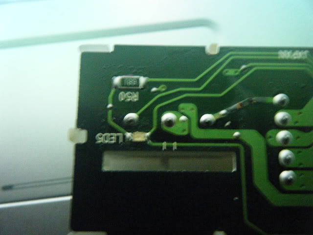
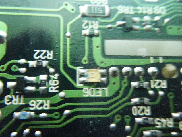
Also, like I said in the tutorial above, the factory resistor values are often printed on the resistors themselves. You may be able to use the numbers printed on top of the resistors to find out if the LED will blow or not.


Ryman
Posts: 121
Joined: Thu Feb 25, 2010 11:34 pm
Car: 2001 Infiniti QX4

Post

premature failure would be like what? Days, months any idea cuz I don't have a multimeter and eventually I need to get one but don't want to get one right now but if it's smarter than i'll pick it up today

Ryman
Posts: 121
Joined: Thu Feb 25, 2010 11:34 pm
Car: 2001 Infiniti QX4

Post

k ran into some problems i put all the lights on the board.... plugged it in, tried it out... it worked but then I went to go put the switches on top of the board and it wasn't aimed properly so it crunched the LEDs off the board taking some of the board with it, including the part of the board that held the solder to it. So i tried for about five hours to figure out how to solder the LEDs onto the circuit board directly without those pieces that I took off and I couldn't figure out a way.1) Anyone know how to solder directly onto a circuit board? if you don't understand I'm saying I don't have those metal pieces that holds solder into place2) IF I can't resolder or repair the board then where do i go online to get the cheapest replacement circuit board?

User avatar
Pwnin O'Brien
Posts: 1717
Joined: Wed Jun 24, 2009 1:10 pm

Post

Ryman wrote:k ran into some problems i put all the lights on the board.... plugged it in, tried it out... it worked but then I went to go put the switches on top of the board and it wasn't aimed properly so it crunched the LEDs off the board taking some of the board with it, including the part of the board that held the solder to it. So i tried for about five hours to figure out how to solder the LEDs onto the circuit board directly without those pieces that I took off and I couldn't figure out a way.1) Anyone know how to solder directly onto a circuit board? if you don't understand I'm saying I don't have those metal pieces that holds solder into place2) IF I can't resolder or repair the board then where do i go online to get the cheapest replacement circuit board?
Google 'how to repair PCB trace' or 'how to repair a board trace' and that should give you lots of ways to replace the board trace that you pulled up.

Ryman
Posts: 121
Joined: Thu Feb 25, 2010 11:34 pm
Car: 2001 Infiniti QX4

Post

So i got a couple questions Has anyone had experience with conductive pens because I was trying to figure out if I could use the conductive pen and let it dry and then solder onto the conductive ink left by the pen. Will the solder stick? Will the ink just melt? Secondly I was wondering if anyone knew of any place to get the armrest or switchpack for an 01 qx4 door other than ebay? (something cheaper and new, not used)

Ryman
Posts: 121
Joined: Thu Feb 25, 2010 11:34 pm
Car: 2001 Infiniti QX4

Post

k so i'm back to giving this mod a shot... i was wondering to solve the clearance issue if these lights would work http://www.oznium.com/plcc-2 or are would they not solder onto the board? i know that these bulbs are used to do dash light mods for some cars but wondering if it will even illuminate?

User avatar
Pwnin O'Brien
Posts: 1717
Joined: Wed Jun 24, 2009 1:10 pm

Post

Ryman wrote:k so i'm back to giving this mod a shot... i was wondering to solve the clearance issue if these lights would work http://www.oznium.com/plcc-2 or are would they not solder onto the board? i know that these bulbs are used to do dash light mods for some cars but wondering if it will even illuminate?
Those will definitely work and they will prevent any clearance issues. You simply just solder those like the factory SMT LED's were soldered to the board. SMT LED's are a little harder to solder down while trying not to hit the LED itself with the iron. Just make sure you check the polarity of the bulbs and solder them accordingly. Also, the typical voltage for the different colors will vary so you may still need to modify the resistances depending on the color you will purchase.

Ryman
Posts: 121
Joined: Thu Feb 25, 2010 11:34 pm
Car: 2001 Infiniti QX4

Post

thanks a lot man.... lol now i just have to order a new switch pack

Ryman
Posts: 121
Joined: Thu Feb 25, 2010 11:34 pm
Car: 2001 Infiniti QX4

Post

K sorry I forgot to put this but on my switch pack the two leds in the middle (the two that control the driver and passenger side window) are 4 pin leds I was wondering if there were any products out there that are like the surface mount leds? OR if you can make the surface leds or the 2 pin ones work with the 4 pin connection?

User avatar
Pwnin O'Brien
Posts: 1717
Joined: Wed Jun 24, 2009 1:10 pm

Post

Ryman wrote:K sorry I forgot to put this but on my switch pack the two leds in the middle (the two that control the driver and passenger side window) are 4 pin leds I was wondering if there were any products out there that are like the surface mount leds? OR if you can make the surface leds or the 2 pin ones work with the 4 pin connection?
I'm fairly certain that even though they are four-pin SMT LED's from the factory I think they are still only two-sided polarity (positive one side, negative the other side). I know that some use two LED's in one LED just for brightness but your new ones will likely just be a single LED. If you are unsure it's best to plug the switch pack into the door and turn the key to ON (without starting the vehicle) and then measure the voltage at each side of the factory LED's with a multimeter.

If you post a close-up picture of the LED's in question I can tell you how to solder it.

Ryman
Posts: 121
Joined: Thu Feb 25, 2010 11:34 pm
Car: 2001 Infiniti QX4

Post

k thanks pwnin i'll order the new packs and take some pics when i get them in big help thanks

Ryman
Posts: 121
Joined: Thu Feb 25, 2010 11:34 pm
Car: 2001 Infiniti QX4

Post

k so i got the passenger side switch pack in and said i would post pics so here they are the first one is the two prong which shouldn't be too hard (hopefully) but the second one is the four pin one and the problem i'm going to have with that is the clearance again. i'm not sure if i can wire surface mount leds to the four pin set up over there any help on suggestions or slim leds would be helpful.
Image

Image

User avatar
Pwnin Obrien
Posts: 50
Joined: Wed Apr 14, 2010 1:08 pm
Car: 2003 Nissan Pathfinder
Location: New Jersey

Post

the one in the second pic just looks like two-terminals since I only see two traces going to it. Do this: if you have a multimeter, check for continuity between the two terminals on each side to see if they are connected. From the picture it looks like what I described before, two LED's in a single unit.

The first picture is a little confusing (due to the blurriness). It looks like a single LED with three traces going to it? If that's the case, check and see if there is continuity between the two traces that share a side.

Ryman
Posts: 121
Joined: Thu Feb 25, 2010 11:34 pm
Car: 2001 Infiniti QX4

Post

oh ok i'll do the continuity thing and get back to you

Ryman
Posts: 121
Joined: Thu Feb 25, 2010 11:34 pm
Car: 2001 Infiniti QX4

Post

k so i checked for continuity and the result was that the bottom left and the top right terminals were connected and that was all... i checked all of the terminals... not sure what that means.... if you can give me a little more instructions

User avatar
Pwnin O'Brien
Posts: 1717
Joined: Wed Jun 24, 2009 1:10 pm

Post

Ok, try this: plug the switch pack back into the door (with the PCB exposed like in the pics above) and turn your car to ON (without starting it). Now test each of the four terminals on the LED. We just want to figure out which terminals are the positive and negative terminals. Just test each terminal against each other terminal to figure out which is which. I can already tell from the pic that the voltage feed is coming in at the trace that goes into the top of the LED since it has the resistor in series with it (the black resistor that has 511 stamped on top).

chinook1352
Posts: 21
Joined: Tue Mar 23, 2010 8:47 am
Car: 2004 Nissan Pathfinder

Post

Hey Pwnin,

Quick question. I'm looking at the Super Bright LEDs website, and they have several different component LED intensities from 1500 mcd to 18000. Which should I go with for the switch panel to maximize the viewing angle and brightness?

User avatar
Pwnin O'Brien
Posts: 1717
Joined: Wed Jun 24, 2009 1:10 pm

Post

chinook1352 wrote:Hey Pwnin,

Quick question. I'm looking at the Super Bright LEDs website, and they have several different component LED intensities from 1500 mcd to 18000. Which should I go with for the switch panel to maximize the viewing angle and brightness?
I went with the 18,000mcd LED's which have a pretty small viewing angle. It really depends on how bright you want your buttons and how much time you are willing to spend aiming the LED's. You always have the option of lightly sanding the top of the LED's to increase the viewing angle. The 18,000mcd LED's are really really bright, I mean they light up a LOT of the door (above the switch packs). They are bright enough that you can tell they are on during the day. IMO the LED's aren't difficult to aim if you just compare the LED location to the little light windows on the switches, it may take a few tries though.

chinook1352
Posts: 21
Joined: Tue Mar 23, 2010 8:47 am
Car: 2004 Nissan Pathfinder

Post

Awesome! Thanks again.

User avatar
Towncivilian
Posts: 4995
Joined: Sun May 23, 2010 10:21 am
Car: 2001.5 Pathfinder SE 3.5L 2WD A/T
2007 Altima 2.5L CVT
2012 Sentra 2.0L CVT Special
2012 G37 Sedan 7A/T
Location: Florida, USA
Contact:

Post

My LEDs require 530 ohms of resistance. The factory resistor for the factory window LED is 511 ohms. Will the 29 ohm difference significantly shorten the LED's life, or should I find a resistor to wire in series?

EDIT: I'll just buy some resistors to raise the resistance. What ohm resistor will I need to reduce a 1500-ohm resistor to around 530?

User avatar
Towncivilian
Posts: 4995
Joined: Sun May 23, 2010 10:21 am
Car: 2001.5 Pathfinder SE 3.5L 2WD A/T
2007 Altima 2.5L CVT
2012 Sentra 2.0L CVT Special
2012 G37 Sedan 7A/T
Location: Florida, USA
Contact:

Post

I decided to use the stock resistors for the rear LEDs and they work fine and are bright enough.

I soldered on a 68-ohm resistor to the 471-ohm stock resistor and left the stock LED on for testing. I plugged it in and it lit up. Both the resistor and stock LED got pretty hot, but the LED did not burn out. Is the resistor supposed to heat up significantly?

EDIT: I was soldering resistors in parallel. I'm a moron. I'll just get some LEDs that will work fine with the factory resistors.

chinook1352
Posts: 21
Joined: Tue Mar 23, 2010 8:47 am
Car: 2004 Nissan Pathfinder

Post

Hey Pwnin I have a question. On my door switch pack my voltage readings for the factory SMDs were kind of weird. The passenger side and lock/unlock button all read normally, around 3.5V each on positive end. But the driver's side switches read 28.6V on the top and around 24.2V on the bottom of each LED. There was no positive or negative. Is the voltage of those two the difference between the two? Or do I need to change the range on my multimeter? If you could help me out I'd appreciate it. Thanks!

jpedderson
Posts: 63
Joined: Tue Jul 17, 2007 5:00 am
Car: 2001 Nissan Pathfinder LE 4WD
Location: (Houston, TX)

Post

Where can I find the resistance needed for the LEDs based on their specs?

What luminosity LEDs did you use? (found answer...duh)

What are the factory originals rated at?

User avatar
Towncivilian
Posts: 4995
Joined: Sun May 23, 2010 10:21 am
Car: 2001.5 Pathfinder SE 3.5L 2WD A/T
2007 Altima 2.5L CVT
2012 Sentra 2.0L CVT Special
2012 G37 Sedan 7A/T
Location: Florida, USA
Contact:

Post

jpedderson wrote:Where can I find the resistance needed for the LEDs based on their specs?

What luminosity LEDs did you use? (found answer...duh)

What are the factory originals rated at?
You can find out resistance required for LEDs here.

In my 2001 SE 3.5L, these LEDs work perfectly without requiring any additional resistors.

jpedderson
Posts: 63
Joined: Tue Jul 17, 2007 5:00 am
Car: 2001 Nissan Pathfinder LE 4WD
Location: (Houston, TX)

Post

Sweet. Thanks!

How do they compare in brightness to original?

User avatar
Towncivilian
Posts: 4995
Joined: Sun May 23, 2010 10:21 am
Car: 2001.5 Pathfinder SE 3.5L 2WD A/T
2007 Altima 2.5L CVT
2012 Sentra 2.0L CVT Special
2012 G37 Sedan 7A/T
Location: Florida, USA
Contact:

Post

jpedderson wrote:Sweet. Thanks!

How do they compare in brightness to original?
I haven't got any pictures, but I will take some soon. They're much brighter than the original green LEDs. Looks much cleaner.

User avatar
Towncivilian
Posts: 4995
Joined: Sun May 23, 2010 10:21 am
Car: 2001.5 Pathfinder SE 3.5L 2WD A/T
2007 Altima 2.5L CVT
2012 Sentra 2.0L CVT Special
2012 G37 Sedan 7A/T
Location: Florida, USA
Contact:

Post

So when I was doing this mod ages ago, I managed to lift two traces, one in each of the two "AUTO" buttons. As a result, the LEDs for those two buttons are intermittent - sometimes they work, sometimes I have to press them and they light, and when I go over a bump or something they cut out again. Any easy way to fix this? It seems that the trace closer to the passenger side (if looking at it as installed) controls the one on the far (driver) side too, since if it's not making contact the other will not light (or maybe it's cause I have two traces lifted and they both make intermittent contact). I'm a bit afraid to take apart the switch pack in fear of damaging the two middle buttons' traces further.


Return to “Nissan Pathfinder Forum / Infiniti QX4 Forum”