This is my second turn switch and for the last two months, I have the same original problem again. I am suprised that I am the only Rogue owner in this Forum, who has such a problem with the turn signal (and it is the second switch that malfunctioned).
I was sure that the problem is not related to the computer (which regulates the flashing speed and sound) or a failed bulb. I was also sure that there was an electrical or mechanical problem with the switch itself. I could go to the dealer and ask them to change the switch, but first I have to "convince" them that the switch needs to be replaced than wait for one or two weeks for the part to come and than a second appointment to replace the switch and next year I am sure that second switch will malfunction...So I decided to open the switch and see what is wrong.
First I found out how to remove the switch from the FSM. At first I thought I need to remove the steering wheel, disconnect airbag without deploying

So here is how to remove the switch and clean it:
1. You need to remove the steering wheel column cover. You can follow the steps on the FSM. Just remove steering lock escutcheon, three screws (they were Philips screws, not torx) and the top and bottom cover pieces (no need to remove the knee protector).
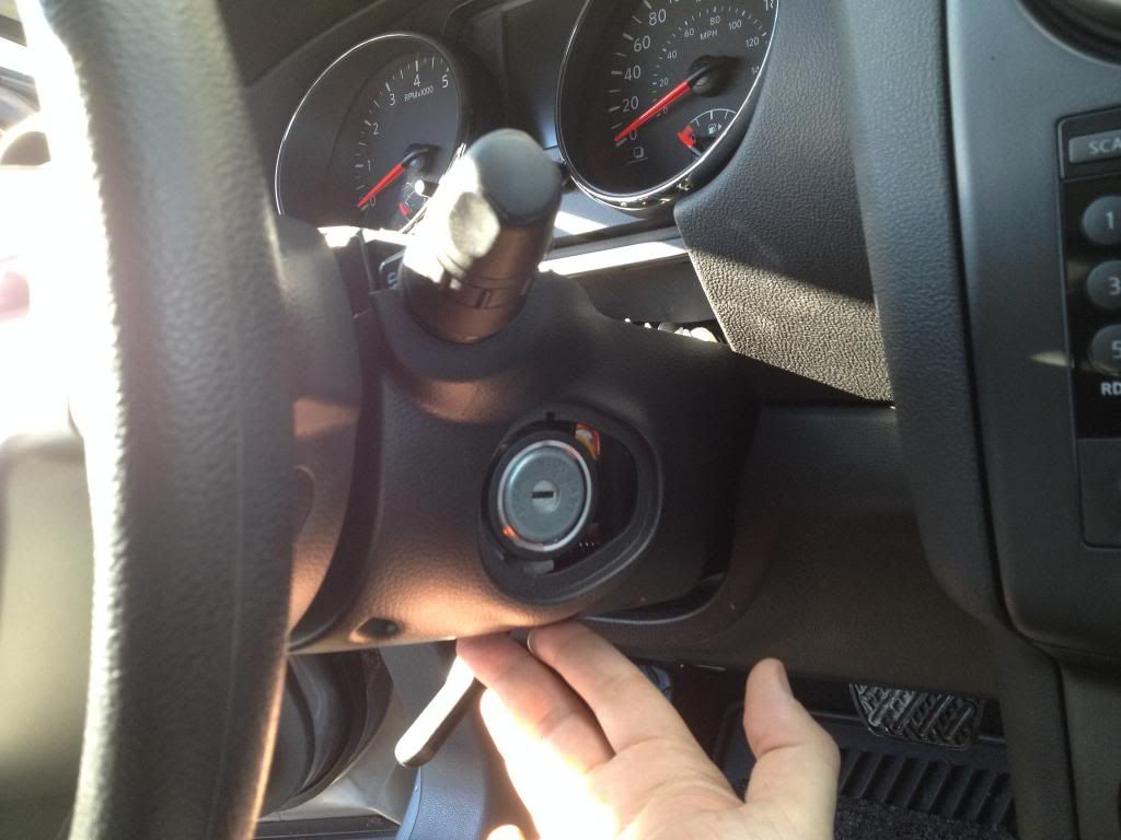
Here is the bottom cover. The three screw locations are circled in red:

2. Press the two plastic pawls. Red circles:

You don't even have to disconnect any wires or connectors, they are automatically disconnected when you pull the switch:

3. Here is the switch. Now take your time and be careful. There are two sides. I call them: Electronic and Mechanical (I wrote ''E'' and ''M'' on the picture).

I recommend to open the Electronic part first to inspect and clean. I didn't open the Mechanical part, but I am pretty sure there is a high risk of breaking or loosing a moving part and a high chance of doing something wrong when putting them together. Remember, that switch has many axes: forward, backward, up, down and turns around central handle axis...that means many grease covered complicated joints and sliders...
4. Two Philips screws hold the Electronic cover (see the red circles on the picture above). Remove the cover and carefully pry the white plastic case to pop up the circuit board. Watch the wire that is soldered to the board (if you have fog light, you have those wires).

Please be careful. Don't shake or move the assembly anymore. Many movable parts will be exposed:

5. Here is the inside of the Electronic part of the switch. Here you can see the double pinned metal contacts and thier matching surcafes where those contacts are sliding on:


They applied a type of grease/lubricant/oil all over the contacts. I am pretty sure they did it for a reason. I think the reason was to protect the contacts from oxidation and dust. There were no dust sticked on the oil (so the switch is pretty much dust proof) and I have no idea why they worried about oxidation of gold plated contacts. Maybe their concern was the friction between the slider contacts and the circuit board would wear the conductive surface...even in that case, my switch was not funcioning properly because of that grease. When you look closely, you can see that there is an oxidation on the turn switch contacts (the most used one). So, since that grease didn't do a good job, I decided to clean it.
I really don't care if the friction due to the lack of grease wears the conductive surface on the circuit board in four five years. It is the next owners problem


Now the switch is cleaner that my ear canal

Put all the pieces back together.
IMPORTANT: Try to move the switch arm left right, backward and forward slowly to see all the plactic pieces with contacts are moving properly before closing the assembly.
Now my switch is working without any problem.