This is what I did on my 2011 QX (start to finish):
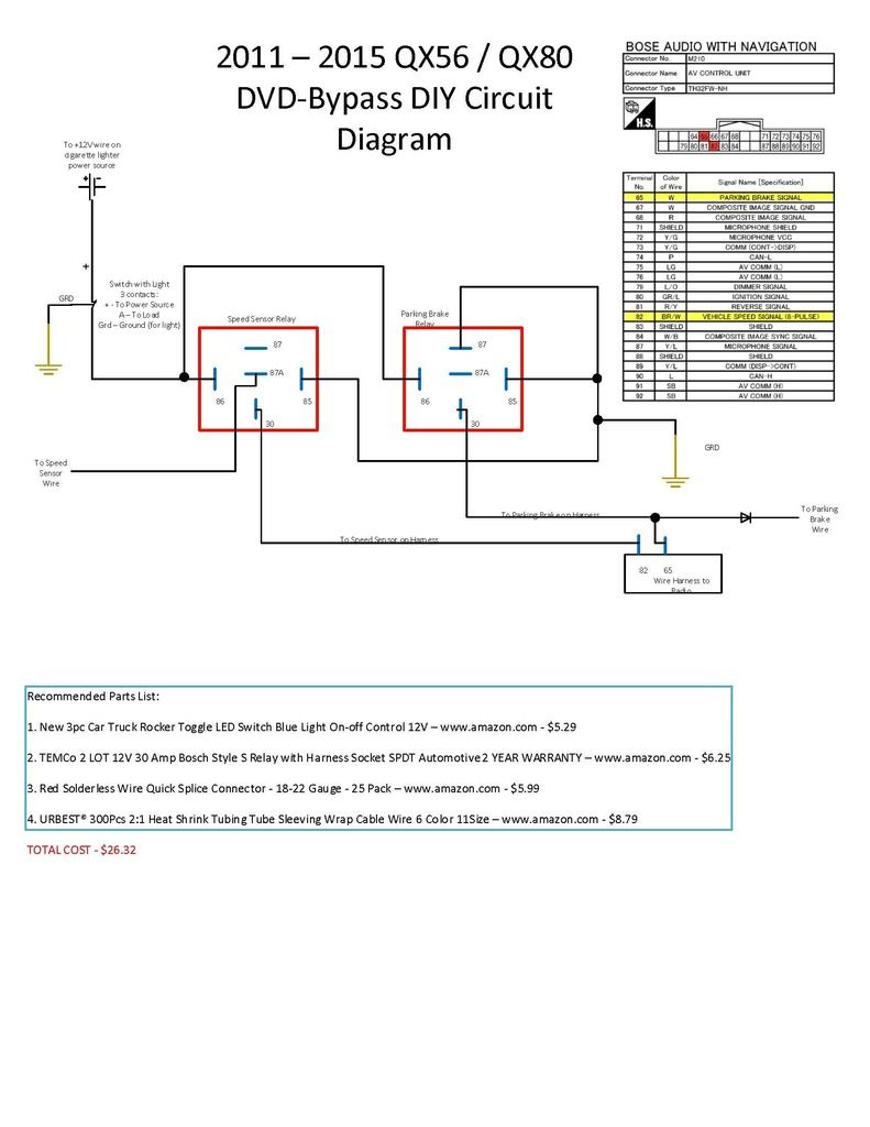
The only difference on the 2011+ QX & The Armadas is the Parking Brake Signal wire location on the 32-pin connector. On the 2011+ QX the wire is on pin #65. On the Armadas, it's pin #80.
I'm going to try to be very detailed in these instructions, but please let me know if something doesn't make sense, and I'll try to explain it further.
First of all, you should read this thread in its entirety (if you haven't done so already). Then follow instructions below.
These are the best instructions for taking the interior apart:
https://docs.google.com/file/d/1AhhyMi3 ... sp=sharing
Here is the Audio Video Service Manual for the QX56. Page 51 shows the terminal layout:
http://www.nicoclub.com/FSM/QX56/2011/AV.pdf
You can try your luck with a screw driver wrapped in cloth of some sort. Or, you can spend $5 for these interior disassembling pry tools for the center console:
http://www.harborfreight.com/4-piece-ny ... 69668.html
I soldered everything together to make secure connections. If you don't know how to solder, don't worry. It's not that hard. Get the cheapest soldering iron, solder, and flux from Rat Shack, watch a couple of youtube videos and practice on stuff you don't mind messing up on first. After 15-30 minutes of practice, you should be a pro . If you're still not comfortable soldering, find someone who is and have them do it for you.
Buy a DPDT switch for $4 from Rat Shack like this one:
http://www.radioshack.com/product/index ... Id=2062525
Get a decent pair of small wire strippers.
Get two feet of CAT5 or CAT6 (solid not stranded) Ethernet cable and take the sleeve off. You should now have 4 twisted pairs (blue/green/brown/orange). You can discard one pair (I discarded the blue). I used the green pair for ground, the brown pair for the wires going to the AV Control Unit, and the orange pair for the wires going away from the AV Control Unit. Strip an 1/8th of an inch from all wires to be used. With the solid strand of all twelve wire ends exposed, add a tiny bit of flux to each wire, then "tin" each one, and while you're at it, tin all six connectors on the DPDT rocker switch too. Tinning means getting solder onto the wires or connectors...kind of like prepping what you're working on. It makes it a lot easier to make connections whilst working in your expensive luxury SUV.
Once you have the AV Control Unit wires cut (1/8" exposed wire), tin them too.
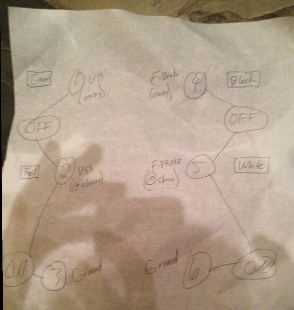
The following numbers represent the back connectors of the DPDT switch. Wire it up like this:
1 4 (1 = Brown ethernet wire, 4 = Brown/White ethernet wire)
2 5 (2 = Orange ethernet wire, 5 = Orange/White ethernet wire)
3 6 (3 = Green ethernet wire, 6 = Green/White ethernet wire)
Solder these to the corresponding AV Control Unit wires below before you wire them to the DPDT rocker switch.
#1 is VSS away from AV (Brown/White wire at pin 82 on the 32 pin connector)
#4 is Parking Brake away from AV (White wire at pin 65 on the 32 pin connector)
#2 is VSS TO AV (Brown/White wire at pin 82 on the 32 pin connector)
#5 is Parking Brake TO AV (White wire at pin 65 on the 32 pin connector)
#3 & #6 Go to GROUND (which can and should be the same ground)
Note: I used the upper left screw (there are four) that holds in the AV Control Unit for grounding both Green and Green/White ethernet wires. I also soldered these two wires together. The exposed portion of them can be an inch long so you wrap them around the grounding screw securely.
The following picture is from Timmbo regarding the same mod (ignore the colors written on the sketch):