Exterior LED Bulbs in the Q

A Q45 forum / Cima forum for the President of Infiniti's lineup. Brought to you by Infiniti Parts USA, your OEM source for Q45 parts!
User avatar
Q451990
Moderator
Posts: 11477
Joined: Tue Jul 23, 2002 8:21 am
Car: 1990 Q45 - 118K, 2022 Toyota 4 Runner, 2004 Frontier M/T - 108K, 2012 Xterra (Mom's), 2023 Rogue (Inlaws)
Location: Columbia, SC
Contact:

Post

I've been playing around with some LED bulbs for the Q. I'm running some "60W" bulbs like this in the front They're available for about $40 a pair on eBay shipped from China:
Image


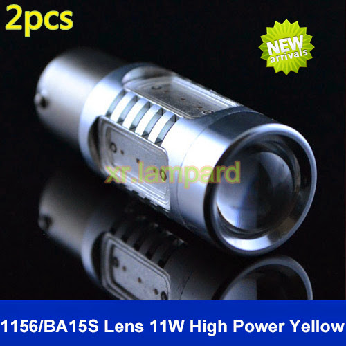
I actually ordered the rears before I found the "60W" bulbs. They're "11W" bulbs available for about $27 a pair shipped from China.
Image

I think they're an improvement to the OEM bulbs. Certainly in response time - and they're finally as bright or a little brighter than traditional incandescent bulbs - which is saying a lot for aftermarket LED bulbs. Because LEDs are so directional - we're just now getting to the point that you can overload a traditional fixture designed for incandescent light that spreads roughly in a globe shape - with very bright more directional LED light.

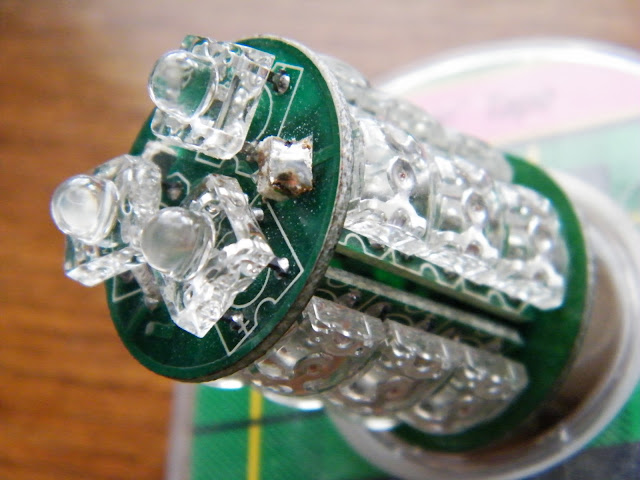
You might notice that I put the wattages of the LED bulbs in quotes. That's because the sellers are listing these at the absolute highest wattage the LED will work at for some very short period of time before it burns out. In practice the LEDs are regulated to consume a fraction of the current of their rated capacity. So for our "60W" LED they're using 12 "5W Cree LEDs. Four forward facing and 8 around the edges.

Here are my measurements for all of the bulbs I'm using. The point is that a "60W LED isn't in any way a danger to pulling too much current vs. the stock 22W bulb. You'll also have to change the stock flasher for the turn signals, and deal with the "bulb out" dash warnings - even with the higher powered bulbs. Note that I didn't list a low+high reading for the LED bulbs. That's because they pull the same current as in the "high" mode.

LED "11W" 1157:
Low = 39 mA (0.47 W)
High = 139 mA (1.67 W)


LED "60W" 1157:
Low = 71 mA (0.85 W)
High = 271 mA (3.25 W)

Incandescent 1157"
Low = 460 mA (05.52W)
High = 1590 mA (19.08W)
Low + High = 1900 mA (22.8W)


http://youtu.be/wQdOzikPVTE
Front Signals - Full Sun - Leds on right of screen.

http://youtu.be/ZG7yRhQiUWA
Front Signals in the Shade

http://youtu.be/XJAfAATPkec
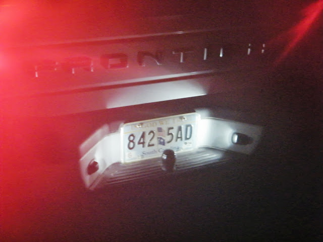
Rear Signals Full Sun - LEDs on Left of screen.

Image
Park Lights - LEDs on right of screen.

Image
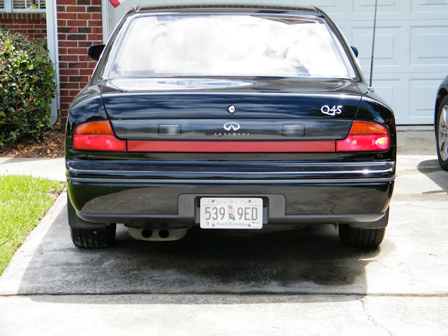
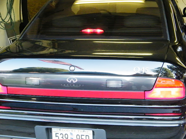
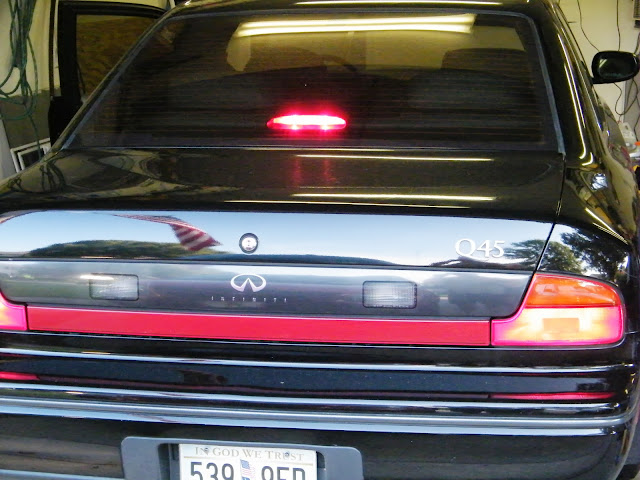
Tail Lights - Full Sun - LEDs on right of screen.


Image
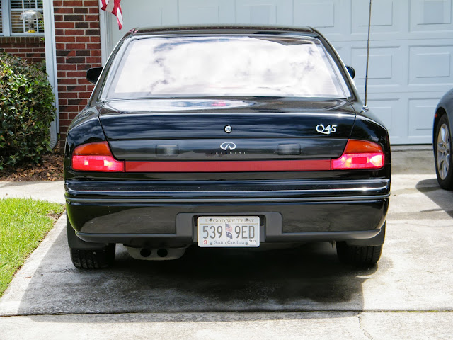
Brake Lights - Full Sun - LEDs on right of screen.

Image
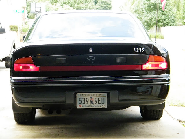
Tail Lights - Shade - LEDs on right of screen.

Image
Brake Lights - Shade - LEDS on right of screen.

One thing I'm noticing is that the greater brightness difference of the LED bulbs grows exponentially with dimmer ambient light. In other words they look "damn that's brighter" at night and only "maybe they're a little brighter" in full sun. I wonder of that has something to do with the fact that LEDs only emit a particular color wavelength vs. incandescent bulbs that fire off a broader spectrum of light?

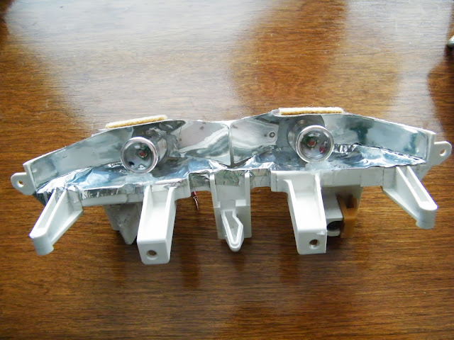
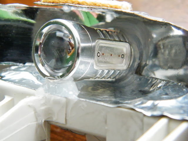
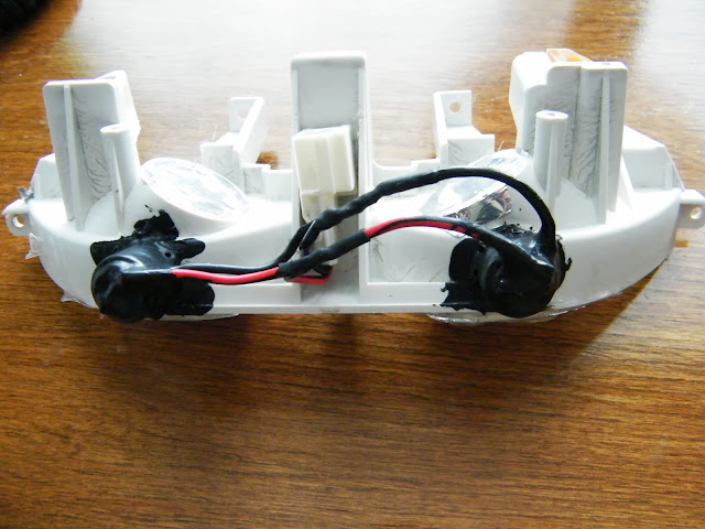
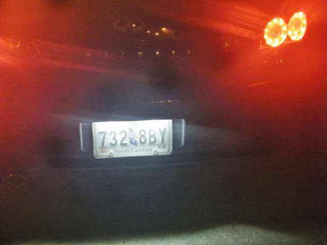
I need to buy another pair of the rear red bulbs... I'm still debating getting 4 of the "60W" units vs. just adding another pair of the 11w ones. The challenge on the rear lights on the Q is that you're looking at the side of the bulb vs. the end. So the forward facing bright Cree LEDs are kind of wasted except that they tend to create a "hot spot" on whatever part of the lens they're hitting. I was able to bend the sockets to face forward a bit and that helped some...

I'm still looking for decent 921s for the third brake light (CHMSL) - but that's been a challenge so far. The ones I've ordered so far have been much too dim. One pair made it to the rear side markers and look good there though. I may have to make something.

Heath


User avatar
Q451990
Moderator
Posts: 11477
Joined: Tue Jul 23, 2002 8:21 am
Car: 1990 Q45 - 118K, 2022 Toyota 4 Runner, 2004 Frontier M/T - 108K, 2012 Xterra (Mom's), 2023 Rogue (Inlaws)
Location: Columbia, SC
Contact:

Post

And to save some time - here is my list of duds.

Paid $2.94 for the pair shipped - too dim:
Image

Paid $3.00 for the pair shipped - too dim:
Image

Paid $6.58 Shipped. Too dim for the CHMSL, but work and fit nicely in the rear side markers.
Image

I was going to use these in the front. They were advertised as white for running lights and yellow for the signal, but they worked exactly the opposite. They also alternated between colors vs. turning the running light off while the turn signal is on. Apparently the alternating style is referred to as "type 1" - while the park-light-off-while-the-signal-is-flashing style is referred to as "type 2" by the sellers that specify. I paid $25 shipped, but seller refunded everything because they work backwards. They were also not as bright as I would have liked.
Image

User avatar
Infinitiguy19
Posts: 7787
Joined: Sat Dec 22, 2007 4:58 pm
Car: 1993 Infiniti Q45 188580 Miles
1994 Infiniti Q45a 240000 Miles

Post

Is their anyway to modify the light bulb sensors (That detect when a bulb is not working) to work with bulbs that draw less power?

User avatar
Q451990
Moderator
Posts: 11477
Joined: Tue Jul 23, 2002 8:21 am
Car: 1990 Q45 - 118K, 2022 Toyota 4 Runner, 2004 Frontier M/T - 108K, 2012 Xterra (Mom's), 2023 Rogue (Inlaws)
Location: Columbia, SC
Contact:

Post

Infinitiguy19 wrote:Is their anyway to modify the light bulb sensors (That detect when a bulb is not working) to work with bulbs that draw less power?
Good question. I have opened them, but I have no idea how they work. My plan is just to add enough resistance to fool them... of course that kills the gains of a lower current drawing light source. If it'll plug in I may use the sensor out of a 94-96 since they only used one brake light bulb per side vs. 2, so that I don't have to put as much resistance in the line.

The other thought is to just put ground or 12V (can't remember what the cluster wants to see) on the line that goes to the instrument cluster.

Heath

User avatar
Haitian_King
Posts: 2868
Joined: Sat Jan 13, 2007 8:20 pm
Car: 1992 Black Infiniti Q45 /w TCS
1995 Black Infiniti Q45
Location: South NJ/PA/Canada

Post

I like it! I'd love to see how they look at night.

maxnix
Posts: 22628
Joined: Mon Jul 22, 2002 8:11 pm
Car: 1995 Infiniti Q45
1995 Infiniti Q45t
2000 Infiniti Q45

Post

Nicely documented, Heath!

User avatar
Q451990
Moderator
Posts: 11477
Joined: Tue Jul 23, 2002 8:21 am
Car: 1990 Q45 - 118K, 2022 Toyota 4 Runner, 2004 Frontier M/T - 108K, 2012 Xterra (Mom's), 2023 Rogue (Inlaws)
Location: Columbia, SC
Contact:

Post

Thanks Brian!

These are the latest ones to arrive.

Image

I paid a whopping $4.88 for 10 of them and they make excellent downlight LEDs. I'm using them for the tag lighting and trunk lighting in both the Q and G. I think it updates everything without looking too aftermarket... I've seen some that are too blue or dim, but these seem like they could have come on the car from the factory.

Heath

User avatar
King Charles
Posts: 125
Joined: Wed Feb 20, 2013 1:28 pm
Car: 1996 Q45
106K Miles
Location: New Bern N.C.

Post

Nice ride.

User avatar
Q451990
Moderator
Posts: 11477
Joined: Tue Jul 23, 2002 8:21 am
Car: 1990 Q45 - 118K, 2022 Toyota 4 Runner, 2004 Frontier M/T - 108K, 2012 Xterra (Mom's), 2023 Rogue (Inlaws)
Location: Columbia, SC
Contact:

Post

So I couldn't find any drop-in bulbs for the CHMSL that looked as bright as the stock halogen, and I wasn't totally in love with the "11w" bulbs for the main brake lights. The reason being that they have one 5w Cree LED facing out of the end, and then "1.5W" of LEDs on each of 4 sides, so you get a bit of a "hot spot" at the end from the more powerful LED on that end. However, they work nicely if they're facing directly out of a reflector! I ended up modifying a spare CHMSL to use them. I pulled the metal reflectors, drilled holes in the back of the plastic frame, cut u-shaped holes in the reflectors, and used clear household silicone to glue the reflectors back in place. I added some aluminum tape to the bottom to help reflect the light up from the bottom LEDs. Then I glued the 1157 LEDs in place with silicone. They were at a bit of an upward angle, which is what I wanted since the majority of what will follow me is taller (SUVs trucks, etc), and I added a bit of silicone at the front to help support them. Then I soldered the leads on to the bulbs and coated them in liquid electrical tape. Note that the wires are soldered on backwards in the pictures. Nissan's trend of bassackward wiring using red for (-) and black for (+) continued in the bulb wiring. I checked the polarity with a meter, but apparently I was remembered wrong - so it's backwards in the pictures - and I had to re-solder them after testing the new light and it not working. I'm going to order a set of the "60W" Cree bulbs for the main brake lights.


Image

Image

Image

Incandescent
Image

LED
Image

User avatar
db_autotek
Posts: 245
Joined: Sun Apr 22, 2007 9:05 pm
Car: 1994 Q45t black & 1993 Miata racer. Previous: 1994 Q45, 1992 Q45.
Location: Hilton Head area, SC

Post

Good stuff! I've been working with led's inside lately and just now getting ready for some exterior replacements. This will definitely help, since I was looking at some of those duds on ebay... But I had the feeling they wouldn't be bright enough.

I did get 7- led 194's into the bumper lamps, but they are too dim since I have my bumper lamps smoked. I am very happy with their placement in the license plate lamps. They are very bright firing straight down, clear lens, just barely have that hint of icey white like the new lexus license plate lamps.

As for the third brake lamp, I've been thinking about this a lot already. Here are my thoughts thus far: I know 1 led bulb is going to be to dim, or have lots of led's and then the bulb won't fit. So im thinking of buying a pair of those 6" white led strips, disassemble the lamp housing, and stick the two led strips in there, up against the back of the housing so it has some room to reflect.

Keep in mind my 3rd is in my spoiler since I have the T. But I have disassembled the lamp before when I was smoking it out. Actually mine will be way easier than if you have the CHMBL on the parcel deck of course.

I'm going to pull the trigger on a pair of the 6" white (or maybe red, the reds are typically emitting much more MCD / light) and I shall report and document that procedure here. If anyone wants to compare led colors, specifications, wavelengths, and output check out www.superbrightleds.com now they are expensive there, so I just go there for information.

User avatar
Infinitiguy19
Posts: 7787
Joined: Sat Dec 22, 2007 4:58 pm
Car: 1993 Infiniti Q45 188580 Miles
1994 Infiniti Q45a 240000 Miles

Post

Any pictures of LED licence plate lamps on a Q?

User avatar
db_autotek
Posts: 245
Joined: Sun Apr 22, 2007 9:05 pm
Car: 1994 Q45t black & 1993 Miata racer. Previous: 1994 Q45, 1992 Q45.
Location: Hilton Head area, SC

Post

Infinitiguy19 wrote:Any pictures of LED licence plate lamps on a Q?
Yeah I got some pics of mine, gimme a sec to fumble with Photobucket

User avatar
db_autotek
Posts: 245
Joined: Sun Apr 22, 2007 9:05 pm
Car: 1994 Q45t black & 1993 Miata racer. Previous: 1994 Q45, 1992 Q45.
Location: Hilton Head area, SC

Post

Infinitiguy19 wrote:Any pictures of LED licence plate lamps on a Q?
Image
finally... geez photobucket
Ok here's a comparison of the 7-led 194 bulbs you see all over ebay on the left, and the oem incandescent bulb on the right. You can clearly see that the incandescent bulb is brighter. But the led lamp produces a nicer color closer to daylight.

One thing I've found with these cheap led lamps is that they use really cheap resistors that tend to blow, rendering the lamp inoperable. I have had to disassemble several of these (easy) and replace the resistor with a soldering iron.

When it's darker outside I will take another pic with both leds in the license plate.

User avatar
Q451990
Moderator
Posts: 11477
Joined: Tue Jul 23, 2002 8:21 am
Car: 1990 Q45 - 118K, 2022 Toyota 4 Runner, 2004 Frontier M/T - 108K, 2012 Xterra (Mom's), 2023 Rogue (Inlaws)
Location: Columbia, SC
Contact:

Post

Here are some pics of the 9 LED flat units in all of our cars... In all of these cases I think they're brighter than the stock incandescent bulb. Like all lighting shots taken at night, I think they look a little brighter in the picture than in person. The tag light housing has very little clearance, so you almost have to use a flat LED unit like these.
Image

Q Tag
Image

Q Trunk... never mind the mess, I haven't unloaded it from a little trip to Charlotte to see a concert last night.
Image

Frontier
Image
These fire sideways out of the housing, and I actually unsoldered the contact part of the board from the LED board and added little pieces of copper wire to use as the contacts so that they'd face out of the window. I used the center conductor of RG-6 cable coax. I don't think they're much brighter than the 5 LED plug in units, but they're at least as good so I left them in there for now...

G35... these fire downward just like the Q.
Image

User avatar
db_autotek
Posts: 245
Joined: Sun Apr 22, 2007 9:05 pm
Car: 1994 Q45t black & 1993 Miata racer. Previous: 1994 Q45, 1992 Q45.
Location: Hilton Head area, SC

Post

The 7-led 194 bulbs from ebay like these: http://www.ebay.com/itm/20x-Car-194-158 ... fc&vxp=mtr on both sides. If you buy these, buy the 10 or 20 pack because they blow like crazy :(

Image

Bonus: a curious orange kitty comes to assess the light for any potential bugs.
Image

User avatar
Q451990
Moderator
Posts: 11477
Joined: Tue Jul 23, 2002 8:21 am
Car: 1990 Q45 - 118K, 2022 Toyota 4 Runner, 2004 Frontier M/T - 108K, 2012 Xterra (Mom's), 2023 Rogue (Inlaws)
Location: Columbia, SC
Contact:

Post

I hope the flat ones like I posted don't blow easily... I'm very happy with the look of them. I ordered an extra 10 of them to have on hand, toss on friend's cars, etc.

User avatar
db_autotek
Posts: 245
Joined: Sun Apr 22, 2007 9:05 pm
Car: 1994 Q45t black & 1993 Miata racer. Previous: 1994 Q45, 1992 Q45.
Location: Hilton Head area, SC

Post

Q451990 wrote:I hope the flat ones like I posted don't blow easily... I'm very happy with the look of them. I ordered an extra 10 of them to have on hand, toss on friend's cars, etc.
Those pics have me sold, I'm going to pick up a set of those 9-SMD flat ones you bought! After working extensively with led's and smd's I can tell you how they fail when they do. The led or smd never fry, its always the resistor or a burned solder joint.

After looking at the flat "T" chip style which uses smd's on ebay, versus the ones I have that use led's and the plastic housing, I am somewhat certain that the "T" chip design is a superior design. First, it uses the surface-mount thick-film resistors as opposed to the axial-lead resistors. These resistors don't blow as easily, and have better heat dissipation than an open air axial-lead resistor. Believe it or not, these lights generate considerable heat, from an engineering perspective. The diode (either smd or led) produces a lot of fine point heat directly at the base. Also, the resistors generate a ton of heat, sometimes enough to burn your finger. We all know heat is the killer of electronics lol. Also, since these lights use a chip as a base instead of the cheap plastic housing, I'm convinced it would be more vibration resistant and dissipate other unknown factors better.

Here's the inside of the 7-led style where I am having to replace a blown resistor. Straight from china, these use a small 1/8-watt resistor at the + and - leads, instead of one nice resistor at the + lead. I think they do this so that it fits in the plastic housing better. Anyway it's a total cheap out, and they blow quickly. To repair, you simply unfold the leads from around the plastic housing, remove the light from the housing, with a soldering iron: remove one resistor and solder a plain lead (piece of wire) in its place, remove the other resistor and solder a 1/4 watt 470 ohm resistor in its place, then just reassemble.

Image
From the top: plastic housing, lamp, my 1/4 watt 470 ohm resistor to solder on there, and the stock 1/8 watt 51 ohm resistor.
Sorry I wrote a novel again, just sharing what I've found in the hopes it can help someone else someday.

User avatar
Q451990
Moderator
Posts: 11477
Joined: Tue Jul 23, 2002 8:21 am
Car: 1990 Q45 - 118K, 2022 Toyota 4 Runner, 2004 Frontier M/T - 108K, 2012 Xterra (Mom's), 2023 Rogue (Inlaws)
Location: Columbia, SC
Contact:

Post

Good to know! Having these things fail prematurely is my one concern... I know they're supposed to last 50,000 hours, but I see LED traffic lights all over town flickering and half burned out and I know the engineering that went in to them was probably far superior to what I'm installing here.

I agree that the circuit board that fits into the socket is a more stable design. I had one with the plastic base that I never could get to make good contact in the tag light housing on my truck.

All of that said... these dinosaurs lasted in the front of the Q from 2005 to a couple of weeks ago for about 35K miles. They weren't as bright as stock, but were adequate I guess. It's amazing how much LED technology has progressed in 8 years.

Image

A red pair like this that I decided to not use in the Q are still in my old '97 Hardbody. I sold it to my neighbor a few years ago and he's put over 150K of hard miles on that truck since then.

Heath

User avatar
Skibane
Posts: 1056
Joined: Wed Apr 26, 2006 5:33 pm
Car: 2000 Q45 AE 110K
Location: San Antonio, TX

Post

Q451990 wrote:I ended up modifying a spare CHMSL to use them. I pulled the metal reflectors, drilled holes in the back of the plastic frame, cut u-shaped holes in the reflectors, and used clear household silicone to glue the reflectors back in place. I added some aluminum tape to the bottom to help reflect the light up from the bottom LEDs. Then I glued the 1157 LEDs in place with silicone.


Image
As long as you're modifying the fixture, installing bare LEDs is another option.

DealExtreme has great prices on "raw" high-power LEDs -

I like to use the versions that are pre-mounted on an aluminum-backed "star" -

Image

Provides easy soldering points for wires, and makes it easy to attach them to a bigger heat sink.

With 3 of 'em connected in series, you don't need a very large power resistor to limit the current when powered from 12 VDC - makes a pretty efficient arrangement.

Some of these LEDs have a very wide viewing angle - which eliminates hot spots when mounted behind the fixture's lens.

User avatar
Q451990
Moderator
Posts: 11477
Joined: Tue Jul 23, 2002 8:21 am
Car: 1990 Q45 - 118K, 2022 Toyota 4 Runner, 2004 Frontier M/T - 108K, 2012 Xterra (Mom's), 2023 Rogue (Inlaws)
Location: Columbia, SC
Contact:

Post

That's a good idea. I think the lure of an almost plug-and-play setup got me started on this. I've had a sleeve of LEDs sitting in my room over the garage for about 8 years now with plans to make custom Q tail lights - but never got confident enough to do it. The only reason I did the DIY fabrication on the CHMSL was because I already had the "11w" 1157s on hand and I wanted to put them to use. If I were to use these star ones, how would one set up a current limiting circuit with a resistor. I have some electronics knowledge from being around my Dad, who was an electronics guy - but I don't have that resource to draw on anymore... I can solder ok, but when it comes to circuit design, we're getting out of my league.

Heath

User avatar
Skibane
Posts: 1056
Joined: Wed Apr 26, 2006 5:33 pm
Car: 2000 Q45 AE 110K
Location: San Antonio, TX

Post

Q451990 wrote:If I were to use these star ones, how would one set up a current limiting circuit with a resistor.
Usually, the LED manufacturer publishes specs for the LED that include (1.) its forward voltage ("Vf") at maximum rated brightness, and (2.) how much forward current ("If") it draws at maximum rated brightness.

Typical specs for a white 100 lumen LED:
Vf = 3.4 volts
If = 0.35 amps (350 mA)

The combined Vf of 3 of these LEDs connected in series would be 10.2 volts:

Image

Typical battery voltage with the engine running is around 14 volts, which is quite a bit higher than the combined forward voltage of the 3 LEDs. So, you'll need to use a resistor to drop the difference between battery voltage and the combined LEDs voltage:

14.0 - 10.2 = 3.8 volts

This is the voltage you'll want across the resistor.

Since the LEDs and resistor are all connected in series, they all draw the same current. For maximum brightness, we want this current to be 0.35 amps.

Since we now know what voltage and current we want on the resistor, we can figure out its value:

Resistance = Voltage / Current = 3.8 volts / 0.35 amps = approx. 10.9 ohms.

We can now also figure out how much power the resistor will be dissipating:

Power = Voltage x current = 3.8 volts x 0.35 amps = 1.33 watts.

The closest, inexpensive standard power resistor size would be 10 ohms at 2 watts.

User avatar
db_autotek
Posts: 245
Joined: Sun Apr 22, 2007 9:05 pm
Car: 1994 Q45t black & 1993 Miata racer. Previous: 1994 Q45, 1992 Q45.
Location: Hilton Head area, SC

Post

SKibane is exactly right. Here's a link to a resistor calculator for single led's that anyone can use: http://led.linear1.org/1led.wiz Now enter the source voltage of 12 in this case. Then input the "diode forward voltage" of your led, and Skibane is right that the standard Vf of most common led's is 3.4 Vf. Finally input the forward current, this is how many milliamps the led needs to operate, the standard here is 20 ma, but if you have the specifications for your specific led, plug that in here.

Here's an extremely helpful wizard for multiple-led series or parallel setups: bonus: it will even help you with resistor color codes needed! http://led.linear1.org/led.wiz You'll input the same info, plus how many led's you want to use, say 3 or maybe 16 for a whole CHMBL!

I have these tools bookmarked and highly suggest that for anyone working with led's, as they can quickly become very complicated lol!

Well here's something nice I found that could possibly be sufficient as a plug 'n play bulb for CHMBL or my spoiler mounted 3rd bl. It's expensive for a pair, but they do look very well built and would probably take the abuse that brake lights get. They have the built-in load resistors so we don't get that annoying "stop lamp inoperative" on the screen.

http://pages.ebay.com/motors/link/?nav= ... 0875553442
Image
Image

User avatar
Q451990
Moderator
Posts: 11477
Joined: Tue Jul 23, 2002 8:21 am
Car: 1990 Q45 - 118K, 2022 Toyota 4 Runner, 2004 Frontier M/T - 108K, 2012 Xterra (Mom's), 2023 Rogue (Inlaws)
Location: Columbia, SC
Contact:

Post

Skibane wrote:
Q451990 wrote:If I were to use these star ones, how would one set up a current limiting circuit with a resistor.
Usually, the LED manufacturer publishes specs for the LED that include (1.) its forward voltage ("Vf") at maximum rated brightness, and (2.) how much forward current ("If") it draws at maximum rated brightness.

Typical specs for a white 100 lumen LED:
Vf = 3.4 volts
If = 0.35 amps (350 mA)

The combined Vf of 3 of these LEDs connected in series would be 10.2 volts:

Image

Typical battery voltage with the engine running is around 14 volts, which is quite a bit higher than the combined forward voltage of the 3 LEDs. So, you'll need to use a resistor to drop the difference between battery voltage and the combined LEDs voltage:

14.0 - 10.2 = 3.8 volts

This is the voltage you'll want across the resistor.

Since the LEDs and resistor are all connected in series, they all draw the same current. For maximum brightness, we want this current to be 0.35 amps.

Since we now know what voltage and current we want on the resistor, we can figure out its value:

Resistance = Voltage / Current = 3.8 volts / 0.35 amps = approx. 10.9 ohms.

We can now also figure out how much power the resistor will be dissipating:

Power = Voltage x current = 3.8 volts x 0.35 amps = 1.33 watts.

The closest, inexpensive standard power resistor size would be 10 ohms at 2 watts.

Thank you for the explanation!

User avatar
Q451990
Moderator
Posts: 11477
Joined: Tue Jul 23, 2002 8:21 am
Car: 1990 Q45 - 118K, 2022 Toyota 4 Runner, 2004 Frontier M/T - 108K, 2012 Xterra (Mom's), 2023 Rogue (Inlaws)
Location: Columbia, SC
Contact:

Post

Well, I finished my brake/tail light LED conversion tonight. Pictures later... I used the "60w" units like I used in the front, but I couldn't find 1157s on ebay anymore, so I ordered a set of 4 off of http://www.aliexpress.com. This site appears to be a sort of "China Amazon" with mixed online reviews - but my experience with Huizhou GMC Car Light Co., Ltd. was good. Got my bulbs in 16 calendar days (three weekends in there) and for $62 for a set of 4. http://www.aliexpress.com/store/product ... 06535.html

These are "get off me!" bright. My only concern is that the tail light brightness is probably as bright as the stock bulbs with the brake lights on - so I hope drivers aren't thinking I'm riding the brakes... I may disable one bulb per side for the tail lights.

To defeat the "Brake/Tail Lamp Inoperative" warning, the yellow/red wire coming from the sensor has to be disconnected. The sensor works by sending ground out on this wire when a bulb is out - no ground, no warning. The sensor has to remain in place for the brake and tail lights to work because the voltage to these lights passes through the sensor. In typical fashion, I made this more complicated than necessary by finding a female connector under the driver's seat of a Q at the pull-a-part that plugs in to the connector for the sensor. I jumped the wires together on the female connector to complete the circuits for the brake and tail lights, and removed the wires for the sensor-to-dash output. So far this works great and I gained about 0.2VDC of voltage by removing the sensor.

As a side note the circuit is just barely adequate for the stock bulbs (we already knew this)... I checked the voltage at the sockets using the stock incandescent bulbs and the tail lights showed 10.9VDC with the sensor and 11.0VDC without it. The brake lights were showing 9.5VDC with the sensor and 9.7VDC without. The battery read 12.5VDC. So lots of drop from what I assume was minimally adequate wire gauge.

Heath


Return to “Q45 Forum / Cima Forum”