I just picked up an 01 I30L. It has the Bose sound system but no cd-changer.
I have a Sony bluetooth adapter that I used in my previous car so I could wirelessly stream music from my phone through my car stereo. In my previous car (06 Grand Prix), I had a touchscreen nav system with XM. I tapped into the factory XM inputs by splicing in a headphone jack, which then plugged into the output of the bluetooth adapter.
Curious to know if there is anyway I can do something similar with this car. I would have thought that if I had the cd-changer, I could just tap into that, but since I don't...well I am thinking it just can't be done. The only thing that makes me ask is that the headunit has the CD Changer button on it so I would guess there has to be somthing I can work out. Also, I had to tear out the rear pillar covers to get at the rear sunscreen as it wasn't working and wanted to have a look. I noticed some little factory Clarion device mounted to the passenger side pillar behind the cover with a number of wires going to it. No idea what the thing is for but I wonder if it has something to do with the stereo, and whether or not it is something I could tap into. I'm thinking it has something to do with the anentnna in the rear window, but again, just not sure.
The good news to this point is that I got the rear sunscreen working. It was lodged stuck and while trying to remove the rear deck it popped free (nailing me in the forehead). But, I would really like to get some type of aux input going on in this thing, so if anyone has any ideas, I would appreciate it. Thanks!
Interfacing aux input to Bose w/o changer - 01 i30
-
dbaxRonin
- Posts: 106
- Joined: Wed Mar 30, 2011 6:13 pm
- Car: 2016 Infiniti Q50 Red Sport 400
2010 Infiniti G37x AWD Coupe (Traded in)
2001 Infiniti i30L (Traded in)
Re: Interfacing aux input to Bose w/o changer - 01 i30
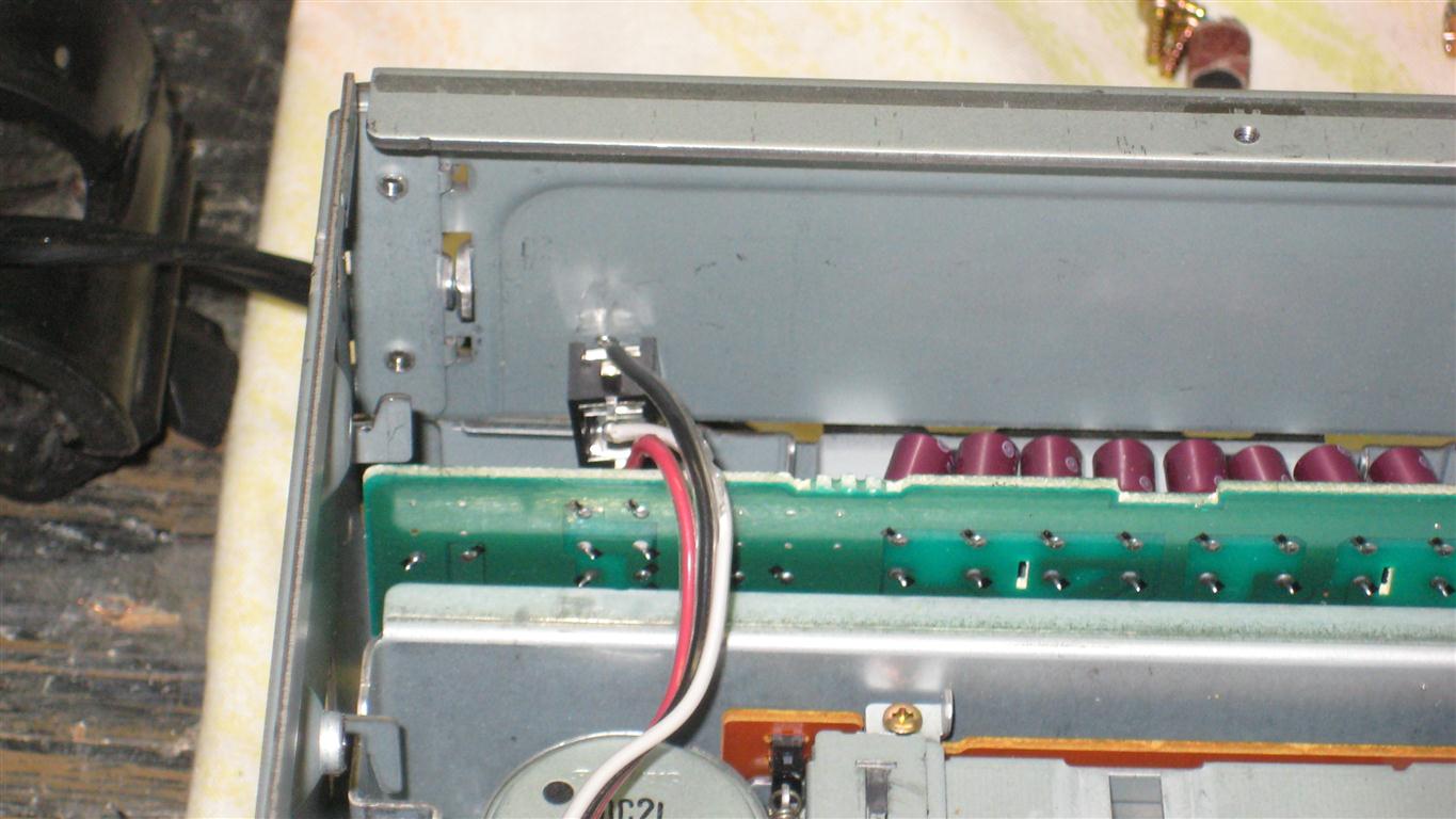
So I got a bit ambitous and tore the radio out tonight. It all started with checking the clock bulbs, but I saw the screws holding in the radio and figured what the hey.
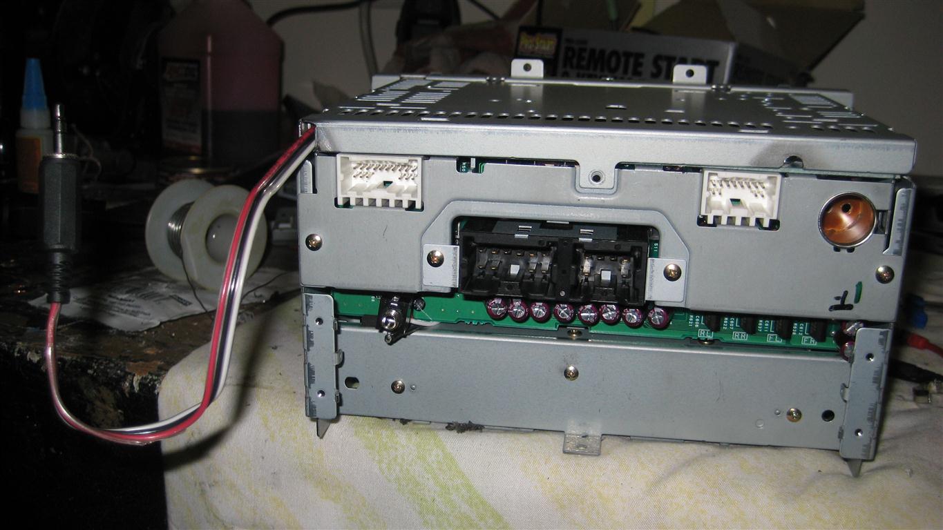
I am curious if anyone knows what the third plug of wires are for. I looked at the Bose schematic found in this link as found in the info section, and it only shows the wiring for the two main plugs...
http://www.moodym.com/maxima/audio/max- ... h-gen.html
Here is a pic of it. The plug I am refering to is the one on the bottom right:
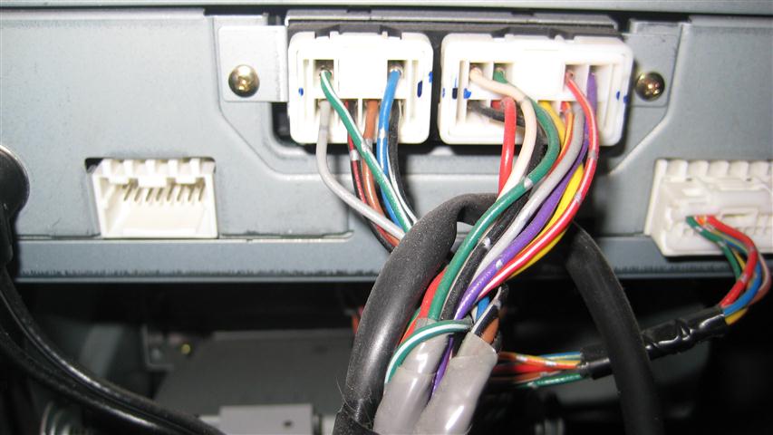
Is the empty plug on the left where the CD changer cables would go if I had one?
I am curious if anyone knows what the third plug of wires are for. I looked at the Bose schematic found in this link as found in the info section, and it only shows the wiring for the two main plugs...
http://www.moodym.com/maxima/audio/max- ... h-gen.html
Here is a pic of it. The plug I am refering to is the one on the bottom right:
Is the empty plug on the left where the CD changer cables would go if I had one?
-
maximapwnage
- Posts: 36
- Joined: Wed Mar 02, 2011 1:36 pm
- Car: Nissan Maxima Completely stock
Re: Interfacing aux input to Bose w/o changer - 01 i30
Correct me if im wrong but that box is an antenna booster
-
dbaxRonin
- Posts: 106
- Joined: Wed Mar 30, 2011 6:13 pm
- Car: 2016 Infiniti Q50 Red Sport 400
2010 Infiniti G37x AWD Coupe (Traded in)
2001 Infiniti i30L (Traded in)
Re: Interfacing aux input to Bose w/o changer - 01 i30
Hoping maybe someone can jump in on where I can find some more information about this Bose HU. I have tried searching up and down but not having much luck.
I ripped apart my cluster tonight to get at two burned out bulbs in my HVAC interface. Since I had everything apart, I decided to flip off the cover on the bottom of the Bose. Turns out that molex plug's pins' are all printed on the circuit board:
________
L+ | L-
R+ | R-
___|GND
___|GND
___|N.C.
___|REQ
TXD|RXD
N.C | N.C
I can wire up a 1/8" stereo jack to the inputs, but I am trying to find out how I can fool the HU into thinking I have a CD changer. I thought maybe I could just run a jumper from TXD to RXD and that might do it, but I don't want to short anything out on a whim.
I presume N.C. is Not Connected(?), and TXD and RXD are transmit and receive respectively. Anyone know what REQ is?
Thanks for any help!

Re: Interfacing aux input to Bose w/o changer - 01 i30
OK, I just picked up a 2001 I30 myself and am currently working on this. I previously had a 1990 Q45 and there was a fantastic thread over in those forums with diagrams for hooking up an AUX input to the CD Changer. It was a mod I ended up doing myself and it worked fantastically.
Their idea was hooking up a momentary switch (on-off switch, many different styles, very cheap) and extending that out to a place you can reach it. You had, basically, left/right and the ground. The momentary switch was on the ground, and hitting your switch would trick the stereo into thinking you had the CD Changer inputting, and hitting it again or hitting another button on your stereo such as Band (AM/FM) would switch it back. The plug was much different, and something like this would require soldering onto the board itself or slicing up a stock CD changer plug to get the wiring.
The Q had a nice 8 pin d-sub plug that you could find at any electronics store.
Here is the link to the Q45 post 94-q45-aux-input-for-mp3-t194403.html
I am doing research and I am so far unable to find proper wiring diagrams for the CD changer plug on the I30 to convert the information. Based on their images for this trick, all you need are left/right positive and negative, aux on signal, and combi on signal. Last post on page 1 is where the goodies are.
EDIT: Looking back through that thread is a blast from the past. We should only need to find out what on these radios equates to an AUX input signal, that is what we will need to ground.
-
dbaxRonin
- Posts: 106
- Joined: Wed Mar 30, 2011 6:13 pm
- Car: 2016 Infiniti Q50 Red Sport 400
2010 Infiniti G37x AWD Coupe (Traded in)
2001 Infiniti i30L (Traded in)
Re: Interfacing aux input to Bose w/o changer - 01 i30
Let me know what you find frentic. I have seen similar threads that do basically that same hack for previous generation i30's that had different Bose HU's than what we have. It seems that on ours however, we don't have this Aux on signal so I really don't know that we can fool ours into thinking there is a cd changer w/o there actually being one. I am sure some electrical engineer might be able to figure it out, but I just don't have those kind of skills.
I have pretty much given up on this project to this point but you give me hope!! Let's hope we can forge some kind of solution because I don't even know where my old CD's are anymore and the radio stations around here suck!! I need my mp3 player!!
BTW...that poor poor diagram I "drew" in my last post is the pin-out for the cd-changer plug. When I get my bulbs for my HVAC and have to rip everything apart again, I will take some pics and make a more manageable image of the pin-outs.
Here is a link to a pinout of a system that the kind of hack you mentioned could work on. The plug on the right is for the cd changer:
http://carstereohelp.net/wireharness_Nissan2.htm
The difference between that and ours is that pins D (Combi on) and L (Aux on) are "N.C." on ours (I still am not 100% what N.C. breaks down to, but considering the number of them, I am still wagering it means Not Connected). I guess it might be worth a try to see what a ground to our "L" pin would do. Maybe I will tinker with it next week.
Re: Interfacing aux input to Bose w/o changer - 01 i30
WOW I just spent the last hour looking for that. I wonder .. I don't trust what is on that board. The CD changer for our cars is almost universal across the Nissan line for that model period, so where one is L=AUX on, it should be the same for ours. It is worth a shot, for sure.
I have not taken my stereo out, if you can recall, was the plug still in the dash for the CD changer? I understand that the wire is already installed, going to the trunk, but is just not connected until you get a CD changer. If it is there, I will go into mine and hack it up and give this a try before the weekend.
The CD changer is PN-2144U and is a Clarion unit, the list of compatible cars is extensive. I would not be surprised if that diagram matches ours. (Wishful thinking? We will see)
Thank you for that information. I need commercial free music in my car ASAP.
-
loystock
- Moderator
- Posts: 2072
- Joined: Sun Sep 21, 2003 9:12 pm
- Car: 10 Honda Pilot
97 Infiniti Q45
03 Infiniti Q45
97 Infiniti I30
06 Infiniti M35 Sports
04 G35 & 99 I30-RIP - Location: San Jose, CA
Re: Interfacing aux input to Bose w/o changer - 01 i30
I added an AUX jack in my son's 97 I30 several months ago for his MP3 player. I did it in a hurry as my son was only home for a couple of hours so I was not able to document it. I bought a jack, SPST switch from Radio Shack (I have wires at home). The AUX jack connection is Tip to L+, Ring to R+ and then a Common connection to L- and R-. I remember connecting the RXD and TXD to the SPST switch. I believe in some HUs, the connection is between TXD (or RXD?) and Ground. However, in my case, the RXD and TXD terminals were not on the PCB so I have to use the CD Changer receptacle pins. I bought sockets from Fry's, crimped with pliers to make them snug with the pins. and then insulated with shrink tubing to prevent short circuit. I'll try to find the wiring diagram I used for the installation.
Re: Interfacing aux input to Bose w/o changer - 01 i30
Did you have this all hooked up to the CD connector? Did you have to ground the TXD and RXD? If you have a diagram of what to do with those two.. I don't think it would hurt to ground both at the same time right?
Thanks for the feedback
Actually re-reading that, it sounds like you just had a switch between the TXD and RXD... That would be a whole lot easier. I just have no idea what those do
Thanks for the feedback
Actually re-reading that, it sounds like you just had a switch between the TXD and RXD... That would be a whole lot easier. I just have no idea what those do
-
dbaxRonin
- Posts: 106
- Joined: Wed Mar 30, 2011 6:13 pm
- Car: 2016 Infiniti Q50 Red Sport 400
2010 Infiniti G37x AWD Coupe (Traded in)
2001 Infiniti i30L (Traded in)
Re: Interfacing aux input to Bose w/o changer - 01 i30
Well..I tried just about every combination of jumping on the cd-changer plug that there is and no luck...just can't get the unit to think there is a changer.
But...
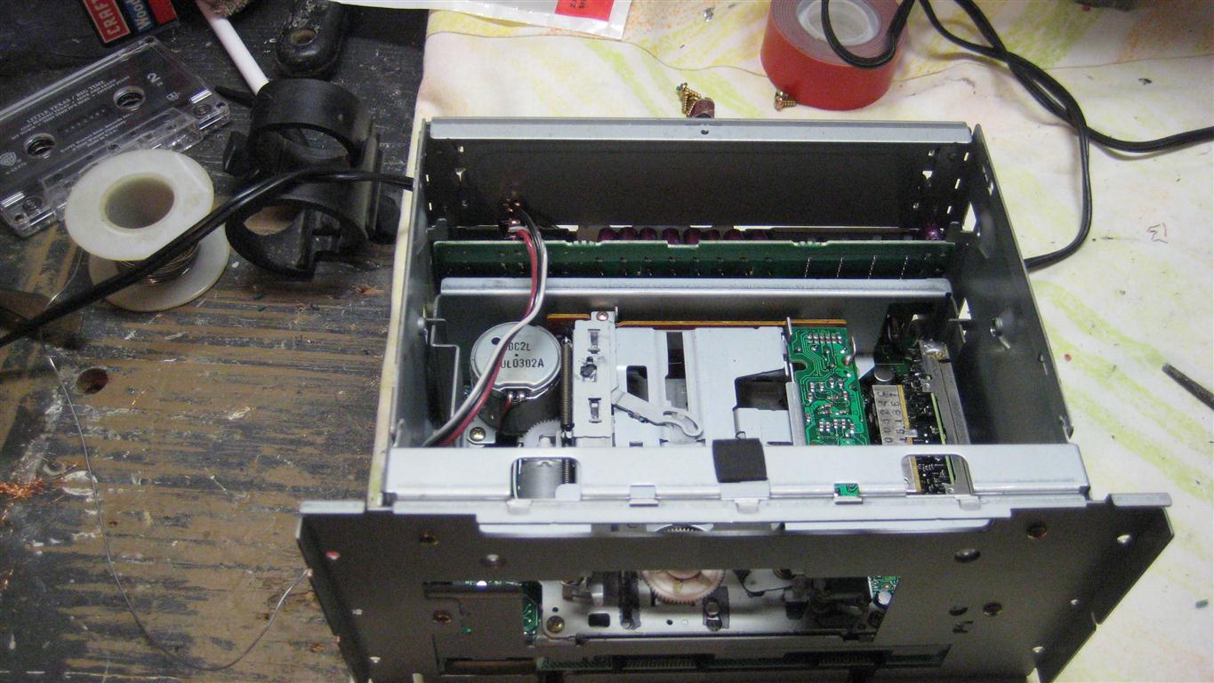
I got ambitious and started to tear down the HU. I removed the CD player and that exposed the tape deck.
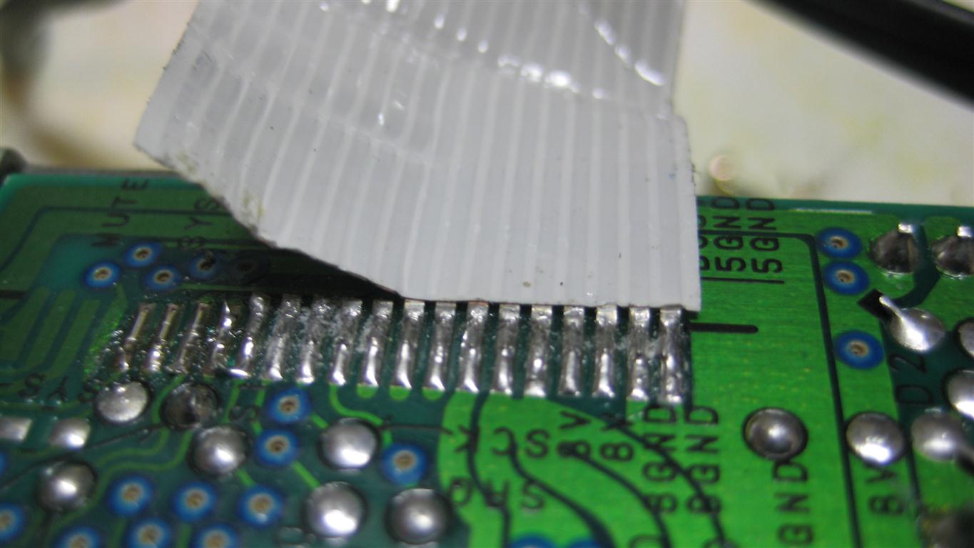
I found the PCB attached to the tape deck had LR, LF, RF, RR, and CMN printed for the ribbon cable leads, which presumably comes from the tape head. Yeah, I went there. I soldered up my 1/8" jack to the corresponding points and found an old tape I had laying around. Plugged it all in and put in the tape, hooked up my phone and to my surprise...I could hear the music from my phone...but it sounded horrific. I played around with it a bit and as it turned out, I was actually recording what was playing on my phone to the tape that was in the deck...hehe OK...that won't work.
So I took it back to the bench and found two more points on the PCB labelled L and R. I figured what's the harm and gave it a go. Money. It actually works! It doesn't sound the best, almost muffled a bit, and I definitely can't crank the phone up or it starts to distort...but it is legible and not too bad. There is some background noise when there is empty space, but I think this is about the only solution that is going to work.
I will fire up some pics once I get everything wrapped up. This does require a bit of surgery to get at the leads, but after that it's golden. Anyway...back to finish the job!
But...
I got ambitious and started to tear down the HU. I removed the CD player and that exposed the tape deck.
I found the PCB attached to the tape deck had LR, LF, RF, RR, and CMN printed for the ribbon cable leads, which presumably comes from the tape head. Yeah, I went there. I soldered up my 1/8" jack to the corresponding points and found an old tape I had laying around. Plugged it all in and put in the tape, hooked up my phone and to my surprise...I could hear the music from my phone...but it sounded horrific. I played around with it a bit and as it turned out, I was actually recording what was playing on my phone to the tape that was in the deck...hehe OK...that won't work.
So I took it back to the bench and found two more points on the PCB labelled L and R. I figured what's the harm and gave it a go. Money. It actually works! It doesn't sound the best, almost muffled a bit, and I definitely can't crank the phone up or it starts to distort...but it is legible and not too bad. There is some background noise when there is empty space, but I think this is about the only solution that is going to work.
I will fire up some pics once I get everything wrapped up. This does require a bit of surgery to get at the leads, but after that it's golden. Anyway...back to finish the job!
-
dbaxRonin
- Posts: 106
- Joined: Wed Mar 30, 2011 6:13 pm
- Car: 2016 Infiniti Q50 Red Sport 400
2010 Infiniti G37x AWD Coupe (Traded in)
2001 Infiniti i30L (Traded in)
Re: Interfacing aux input to Bose w/o changer - 01 i30
Here are a couple pics. I am going to end up re-doing this because the damn headphone jack I used is too short and the bare ground kind of scares me. It was a hack job just to see if it would work. Got a road trip tomorrow so we'll see how well it really works then.
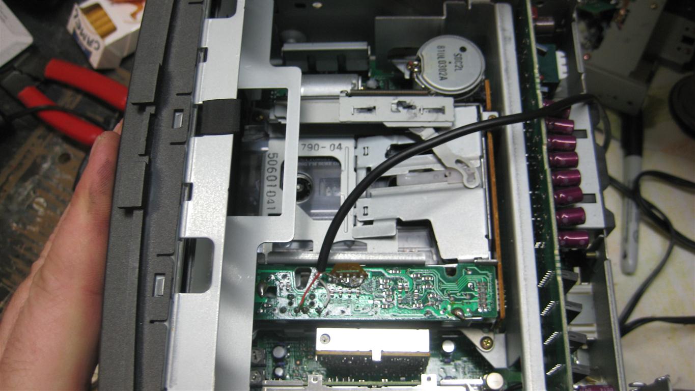
Here is an aerial view with the cd player removed to show where the work on the tape deck was done:
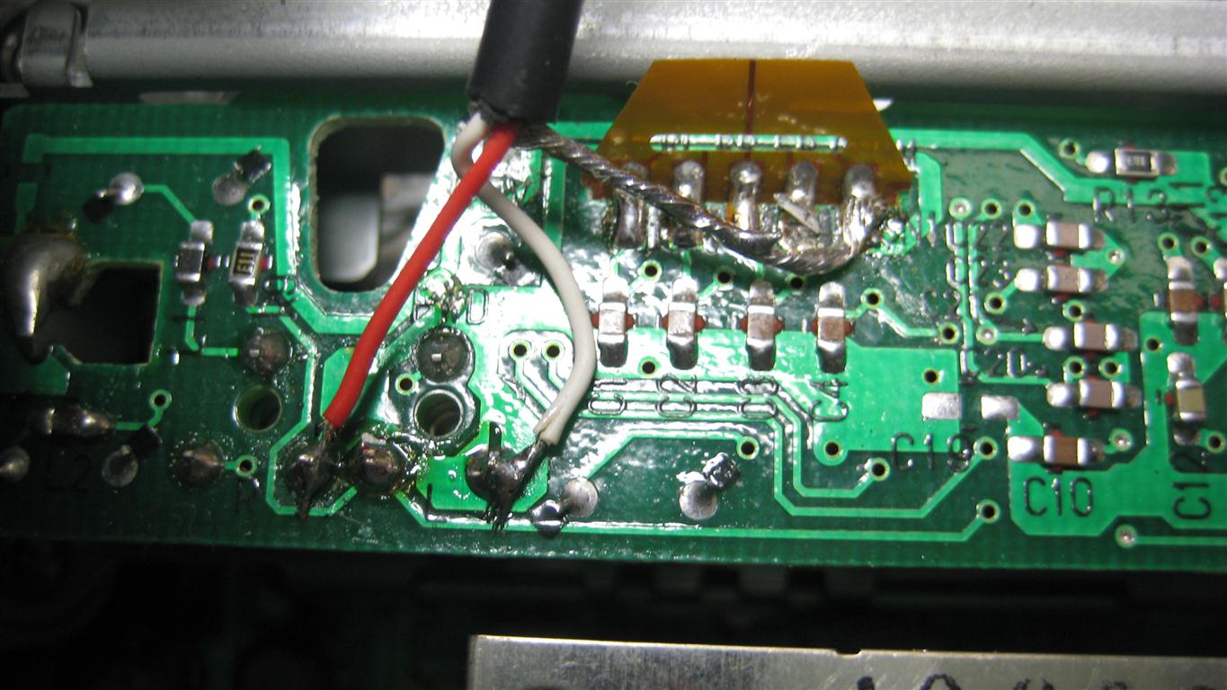
Here is a close up:
Took a video of it in action as well:
http://www.youtube.com/watch?v=vT4RovjRuBI
Here is an aerial view with the cd player removed to show where the work on the tape deck was done:
Here is a close up:
Took a video of it in action as well:
http://www.youtube.com/watch?v=vT4RovjRuBI
Re: Interfacing aux input to Bose w/o changer - 01 i30
I got in there and attempted to throw jumpers on several pins that could work and even grounded several more, nothing would trigger like I wanted it to. I am lost for now, I don't have the knowledge, just the ambition. I will give it another try tomorrow probably.
Re: Interfacing aux input to Bose w/o changer - 01 i30
TXD and RXD are transmit data and receive data, respectively...
OK I think at this point it is safe to say, there is no way this can work without actually having a CD changer. Everything I am reading on these head units is the TXD/RXD lines talk to each other with help from the changer. If you do have a changer, you can run simply left and right audio input, and ground, soldered onto the PCB directly to a 3.5mm jack, the problem is the stereo will still play from your CD changer, so you need a blank CD that can run on a loop so you only get it from your preferred audio source. I am giving up on my project for now. I prefer the clean stock look of OEM stereos but I should be looking at new stereos.
I wish you guys luck in your quest for audio freedom!
 Re: Interfacing aux input to Bose w/o changer - 01 i30
I have a '01 i30t, it has the Bose head unit and all, I'm really wanting to find a way to bluetooth stream or just plain use an aux input for the music, but I've ran into a dilemma, the car won't be mine until about 1 1/2 months, and until then I cannot modify anything on the car, so no head unit replacement or anything. I figured I could just use a cassette-aux input but the cassette player happens to be broken. So I'm wondering there is any ideas out there? Other than replacing the head unit with the same one with a working tape player or using an FM transmitter, they are never as loud as the actual aux input. Thanks!
-
dbaxRonin
- Posts: 106
- Joined: Wed Mar 30, 2011 6:13 pm
- Car: 2016 Infiniti Q50 Red Sport 400
2010 Infiniti G37x AWD Coupe (Traded in)
2001 Infiniti i30L (Traded in)
Re: Interfacing aux input to Bose w/o changer - 01 i30
As we are learning, the options to add an aux input to these radios that don't have a cd-changer are quite limited. Aside from the tape deck hack that I posted above, your only real options are either a tape adapter like you mentioned, a fm transmitter as you also mentioned, or a FM bypass like this one...
http://isimplesolutions.com/universal-s ... -IS32.aspx
The bypass solution would also require an antenae adapter since ours uses a goofy double prong plug. I have never heard how these by pass solutions work so I can't comment on them.
http://isimplesolutions.com/universal-s ... -IS32.aspx
The bypass solution would also require an antenae adapter since ours uses a goofy double prong plug. I have never heard how these by pass solutions work so I can't comment on them.
-
loystock
- Moderator
- Posts: 2072
- Joined: Sun Sep 21, 2003 9:12 pm
- Car: 10 Honda Pilot
97 Infiniti Q45
03 Infiniti Q45
97 Infiniti I30
06 Infiniti M35 Sports
04 G35 & 99 I30-RIP - Location: San Jose, CA
Re: Interfacing aux input to Bose w/o changer - 01 i30
As i have posted earlier, I have had an AUX jack installed in my son's 97 I30. It worked and he's very happy. I found a note in my maintenance record about the actual pin connection. I could have drilled a hole thru the head unit cover but my son just want it besides the shifter. I taped the Switch and Aux jack together.
Please refer to the link, "carsstereohelp.net" posted by "dbaxRonin" as it shows the pin assignment to the CD Changer receptacle, J202. I use Pins A and B for the Aux jack's Tip and Ring, E and F wired together for the Aux jack's Common and then the SPST switch connected to Pins K and L. Depending on where you want to place the Aux jack and Switch, you need 2-3 feet of wiring. Aside from the wiring, you need:
-3.5 mm (1/8") 3-conductor Stereo Jack ((I used Radio Shack 274-0249, 2-pack)
-smallest/practical SPST (Single Pole Single Throw) Toggle switch
-D-Sub Pin, RS-232 Crimp Pin, Female (got it from Fry's Electronics) or equivalent pins or better yet, if you have the exact plug to mate with J202 receptacle.
-smallest diameter heat shrink tubing (to insulate the pins, VERY IMPORTANT TO AVOID SHORT CIRCUIT)
-heat gun to shrink the heat shrink tube over the pin and part of the wire)
-wire stripper and cutter
-long nose pliers (to crimp the wire into pin as well as the pin itself)
*Note 1: Once the head unit is out, you need to lightly crimp the female pins to make them snug against the J202 receptacle's male pins. You may break some in the process. Once the pins are snug, then crimp the respective wire to each pin and label as required. Connect the wiring-pin to respective terminal and then route it to where you want the Switch-Aux jack to be.
Note 2: In some head units, you can actually solder the wires to the terminals on the PCB.
J202 Receptacle Pins (only relevant pins listed)
Pin A: Lch INPUT (+) - this is used to connect with the Tip of the Aux jack (refer to package for Ring, Tip, Common)
Pin B: Rch INPUT (+) - this is used to connect with the Ring of the Aux Jack
Pin E: Lch INPUT (-) - this, together with Pin F are wired to the Common of the Aux jack
Pin F: Rch INPUT (-) - this is connected to the Common of the Aux jack
Pin K: CD-COMBI (RXD) - this is used to connect with the SPST switch
Pin L: AUX-ON SIGNAL INPUT - this is connected to the other side of the SPST switch.
When the Switch is turned ON, it sends a signal to the Head Unit that the CD Changer is ON so input to the Aux jack is then enabled. You may need to increase the volume when using the Aux port.
Re: Interfacing aux input to Bose w/o changer - 01 i30
So what if I do have a CD changer? I know there is a spot for it in the back, I don't have to actual changer but it's an option on the radio, and like I said, there's a space for it in the trunk.dbaxRonin wrote:As we are learning, the options to add an aux input to these radios that don't have a cd-changer are quite limited. Aside from the tape deck hack that I posted above, your only real options are either a tape adapter like you mentioned, a fm transmitter as you also mentioned, or a FM bypass like this one...
http://isimplesolutions.com/universal-s ... -IS32.aspx
The bypass solution would also require an antenae adapter since ours uses a goofy double prong plug. I have never heard how these by pass solutions work so I can't comment on them.
-
dbaxRonin
- Posts: 106
- Joined: Wed Mar 30, 2011 6:13 pm
- Car: 2016 Infiniti Q50 Red Sport 400
2010 Infiniti G37x AWD Coupe (Traded in)
2001 Infiniti i30L (Traded in)
Re: Interfacing aux input to Bose w/o changer - 01 i30
If your car was originally equipped with the changer and it was removed you may be able to use the method that loystock just posted above. If your car still has the changer harness in it, you can just trace the appropriate wires and tap into them without having to tear your HU apart to get at the pins on the PCB.
My car was never equipped with the changer but there is a CD/Changer button on the HU, but all it does is switch to the in-dash cd player. I would think that since they include the pinouts/plug for the CD changer, even though it was never actually installed, that the HU would somehow have the ability to change into changer mode through some trickery...which is basically what loystock's method is all about, but it seems it all comes down to whether or not your radio has the AUX-ON input. Perhaps an electrical engineer can figure out a way to get this working if no AUX-ON is available. I happen to have a friend who is an electrical engineer for GE and just sent him an e-mail to see if he has any ideas on all this. I haven't seen the guy in years and I doubt without doing some actual hands-on analysis he will be able to tell us much, but I thought it worth a try to ask. If I get a reply from him I will be sure to post it up.
If worse comes to worse, the tape deck option I posted about above does work. The sound quality is not superb by any means but it is better than I thought it would be. The one issue I have run into using that method is that if I plug in my charger to my phone and stream at the same time, there is horrific ignition noise. With the charger unplugged though it isn't bad. I do have to turn the bass on the HU all the way down however as it seems to drone out otherwise. I used to have an 06 Grand Prix GXP with Navigation and Sirius/XM. I had hacked into the XM feeds and setup both a standalone XM unit and bluetooth adapter that I streamed my phone through. This tape deck hack on the Infiniti sounds better than that setup did and that was a direct feed input. I tried to hook up my bluetooth to the Infiniti but that unit supresses too much of the volume and even with everything cranked I could hardly hear anything.
Anyway, good luck with whatever you decide to try. I will post back if I hear anything from my buddy.
-
dbaxRonin
- Posts: 106
- Joined: Wed Mar 30, 2011 6:13 pm
- Car: 2016 Infiniti Q50 Red Sport 400
2010 Infiniti G37x AWD Coupe (Traded in)
2001 Infiniti i30L (Traded in)
Re: Interfacing aux input to Bose w/o changer - 01 i30
Good news. I found a CD hack. Not a CD Changer hack, a CD hack. I spent most of the afternoon today playing with the circuits on the HU (I was able to get it into Telephone mode and feed it a signal but it sounded like a**). It seems that there is a way that you can put in a cd and then essentially pause it by closing a circuit from the cd player. With an aux jack's L and R wired into the CD players L and R Out terminals on the main PCB, after you close the circuit, you get full range aux input that sounds crystal clear!! It will require a momentary switch mounted somewhere to close the circuit, but this will definitely work. Best part is, you can restore the use of the CD by just going to another source and then back to CD...then if you want to go back to the aux, you just need to hit the momentary switch again.
I don't have a momentary switch handy and Radio Shack is closed, but I am going to pick one up tomorrow and fire this up. I will get some pics together to show how to do it.
I don't have a momentary switch handy and Radio Shack is closed, but I am going to pick one up tomorrow and fire this up. I will get some pics together to show how to do it.
-
dbaxRonin
- Posts: 106
- Joined: Wed Mar 30, 2011 6:13 pm
- Car: 2016 Infiniti Q50 Red Sport 400
2010 Infiniti G37x AWD Coupe (Traded in)
2001 Infiniti i30L (Traded in)
Re: Interfacing aux input to Bose w/o changer - 01 i30
*&(#*@&@#)(*&#$*(#@&^!!!!
So I was taking out the cable I rigged to the tape deck, which involves removing the actual CD player. Reinstalled it and hooked up the HU and got a CD Error message. Long story short, I ripped a number of the terminals off the ribbon cable that plugs the CD player into the PCB. I fixed the first four by running some jumpers, but #6 was bad too. In an effort to fix that I managed to tear a crap load more of them off and I am running out of dexterity for such small solder points. At least the radio still works. So yeah, this project is officially on-hold and there is a good chance I may not be able to get this fixed.
So I was taking out the cable I rigged to the tape deck, which involves removing the actual CD player. Reinstalled it and hooked up the HU and got a CD Error message. Long story short, I ripped a number of the terminals off the ribbon cable that plugs the CD player into the PCB. I fixed the first four by running some jumpers, but #6 was bad too. In an effort to fix that I managed to tear a crap load more of them off and I am running out of dexterity for such small solder points. At least the radio still works. So yeah, this project is officially on-hold and there is a good chance I may not be able to get this fixed.
-
dbaxRonin
- Posts: 106
- Joined: Wed Mar 30, 2011 6:13 pm
- Car: 2016 Infiniti Q50 Red Sport 400
2010 Infiniti G37x AWD Coupe (Traded in)
2001 Infiniti i30L (Traded in)
Re: Interfacing aux input to Bose w/o changer - 01 i30
Well, I managed to fix the ribbon cable issue and got my cd player working again (after I bid on a whole new HU on ebay =/). It involved a blow torch, a razor blade, and about an hour of fixing shorted solders, but it works fine. So, I was able to tackle the aux input project again and got everything buttoned up this evening.
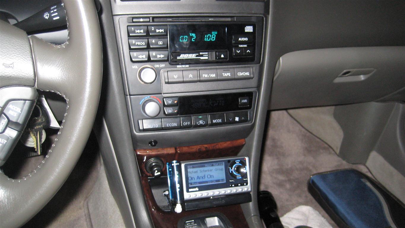
So, here is the low down. First, a list of parts needed to do the job. This may vary depending on how you want to do yours, but I will list what I used. I ended up with a 1/8" female plug on the back of the radio that I plug my stuff into. I used an extension to run from the back of the radio and fed it through a hole on the top of the bin under the ashtray. In that bin, I mounted my Sirius unit and a Sony Bluetooth receiver that I stream my phone through:
Finished product with the Sirius and Bluetooth mounted:
And a demo video. Unfortunately my Bluetooth causes some interference but other than that, it sounds great and works really well.
[youtube]http://www.youtube.com/watch?v=asxIVB67Xoo[/youtube]
If anyone decides to pursue this and has any questions, please feel free to ask and I will help where I can. Good luck!
So, here is the low down. First, a list of parts needed to do the job. This may vary depending on how you want to do yours, but I will list what I used. I ended up with a 1/8" female plug on the back of the radio that I plug my stuff into. I used an extension to run from the back of the radio and fed it through a hole on the top of the bin under the ashtray. In that bin, I mounted my Sirius unit and a Sony Bluetooth receiver that I stream my phone through:
- 1. An open momentary switch. I used http://www.radioshack.com/product/index ... Id=2062508 and mounted it to the panel under the HVAC control unit. Make sure whatever you use has a normal open state connection and not closed. You want the switch to close the circuit when you push the button.
- 2. 1/8" female surface mount headphone jack. Use these if you want a jack to plug your plug into opposed to just having a long cord run from the HU out to the cabin. I used this one http://www.radioshack.com/product/index ... Id=2103452
- 3. Higher gauge copper wire. Enough to run from wherever you want your jack mounted to around the back of the HU and then across the HU to the front of the unit. I used a solid core copper ribbon cable that I had handy, not sure of the gauge but it is probablly around 22. You need something small because the solder points on the PCB are minute`.
- 4. I installed a disconnect between the switch and the HU in the event I ever need to remove the radio again...this is optional but a good idea if you ever need to remove the radio. For this I just used what was handy, which turned out to be a male/female headphone plug:
Male: http://www.radioshack.com/product/index ... Id=2104061
Female: http://www.radioshack.com/product/index ... Id=2104044
- 5. If you plan to install multiple items, you may need some y-adapters. Something like this http://www.radioshack.com/product/index ... Id=2103870. Just make sure whatever you get is stereo and not mono...same applies for all these parts.
- 1. Remove the stereo and HVAC cluster from the car. Going to assume you can do this already, but if you need help, post up or search around. It's not hard, just be carefull when prying out the shifter plate and top vents. This will require some smaller tools to unclip all the plugs from the ashtray, hvac, radio, etc.
- 2. Remove the HU from the cluster. There are a total of 10 screws to do this. There are four larger faced black screws on each side. These were insanely difficult to remove on mine. In fact, I had to use my dremel and cut slots in them so I could use a slotted screw driver to break them loose. Using a philips I was only able to get one of the 8 free...the rest started to strip the head slots. WTF nissan...my lug nuts came off with one hand but these require surgery?!!
The other two screws are located between the HU and the HVAC module. Will require a longer #2 philips to remove...use magnetized driver if you have one so you can lift the screws out. These are used to hold the face plates together and are spaced about 2" apart. Just look down in-between the HU and HVAC and you will see them.
- 3. Once all the screws are removed, you will need to pry and wedge and twist and turn the HU. The holes where the 8 black screws came from are beveled on the inside and sit inside the recessed screw holes of the radio, so you need to wedge the frame a bit to release them. This takes some patience. Also take into consideration that the face plates from the HU and the HVAC interlock a bit. Eventually it will just pop out and you can lift it out of the cage. I think the cuss count on this process was about a 5.
Note: You can instead just remove the ashtray and HVAC modules, which are much easier to remove. The problem is the mounting frame will be attached to the HU and just makes for an obstacle when you are soldering. Also, by removing the HU, it makes it easier to plug into the car when you are testing.
- 4. Once the HU is removed, use a #1 phillips screwdriver and remove the one screw holding on the cover on the bottom of the unit (Its in the middle on the back). Once the screw is out, use a flat blade screwdriver to pry it up around the corners where it is notched to hold.
- 5. With the bottom cover removed, you will be exposed the main PCB of the HU. With the front of the HU facing you, there are a set of pins that the CD player ribbon cable plugs to on the bottom right corner of the PCB. This is where all the wiring needs to be done from to get this to work. There are two rows of pins, 9 pins per row. You should see the labels of the pins printed on the PCB up and to the left of the pins. On the top row, pins 5 and 6 are the "inputs". 5 will be labeled L-OUT and 6 will be labeled R-OUT. Wire your L and R wires for your aux jack to these appropriately. For the ground, I just used one of the studs holding the PCB in place...there is one just to the right of the pin outs.
On the bottom row (with the face of the HU still pointing towards you), the 2nd pin from the left is labeled "RESET". Wire one lead from your momentary switch to this pin, and the other lead from your switch to another ground post.
Here is a photo of all the wiring. The yellow wires are the ones that go to my momentary switch:
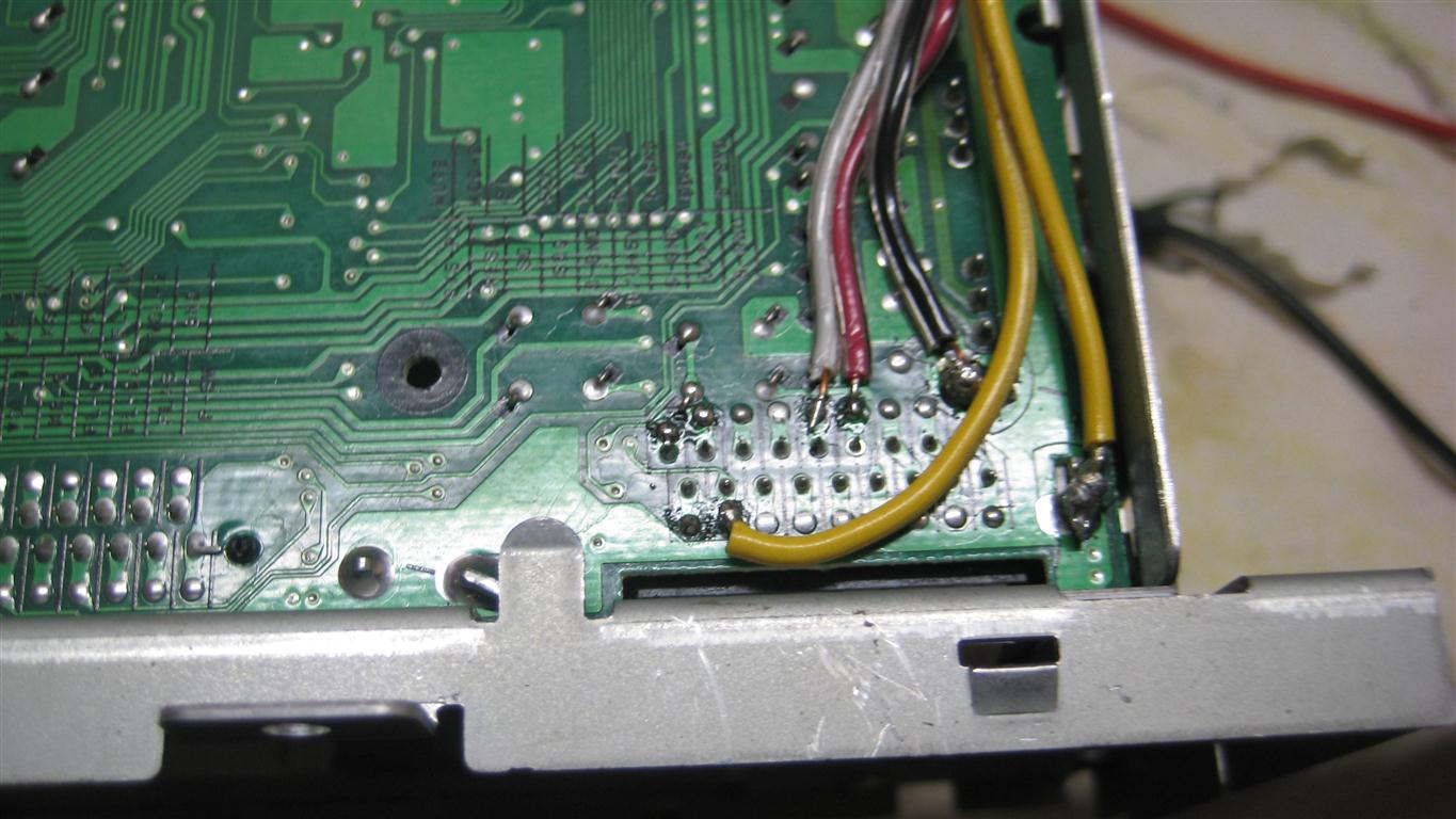
I eventually replaced the yellow wires once I got a real momentary switch. Here is a photo of the plug that will connect to the momentary switch. Note: There are 3 wires on this plug, but you only need two and if you use a headphone jack like I did, you can pick whichever 2 of the 3 leads to use. I just happened to have this plug from a previous project so I reused it instead of making a new one:
I cut out a small notch from the bottom cover plate and just ran the wire out of there:
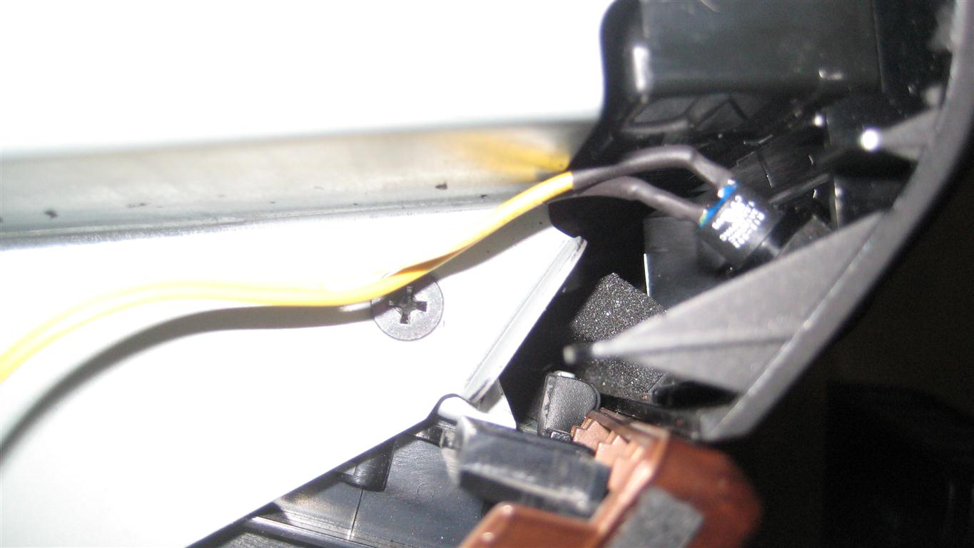
- 6. Once you find a spot to mount your switch, drill away and mount it as needed. I forgot to take a pic of the headphone jack I wired to the momentary switch that plugs into the jack wired on the HU...you will just have to use your imagination.
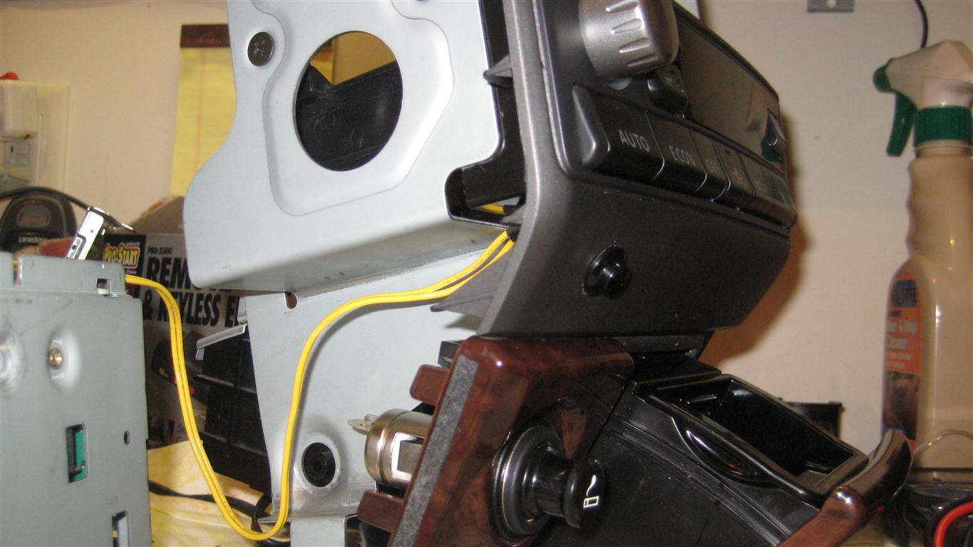
Here is a shot of where I mounted mine:
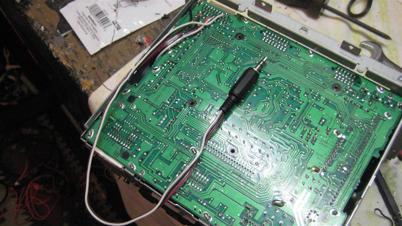
- 7. How you run your aux cable is up to you. Like I said, I just ran my cable to the back and wired it up to a small headphone plug. This way, I can just unplug the cable if I ever need to remove the HU in the future without having to tear out the cable running to the cabin. Here is a pic of it. Notice there is no CD player. You don't necessarily have to remove it to do this step and based on what happened to me as posted previously in this thread, I recommend you don't (but if you do, just be careful of that ribbon cable!)!! If you can snake your wires to the back, you can just remove the back plate and install your plug on there.
Finished product with the Sirius and Bluetooth mounted:
And a demo video. Unfortunately my Bluetooth causes some interference but other than that, it sounds great and works really well.
[youtube]http://www.youtube.com/watch?v=asxIVB67Xoo[/youtube]
If anyone decides to pursue this and has any questions, please feel free to ask and I will help where I can. Good luck!
Re: Interfacing aux input to Bose w/o changer - 01 i30
You guys have so much patience in something like that and I respect that but why not just get a new headunit with an AUX jack? If its for the sake of tinkering and hacking away then I'm all for it but I personally would save all that time and just install a new radio unit.
-
loystock
- Moderator
- Posts: 2072
- Joined: Sun Sep 21, 2003 9:12 pm
- Car: 10 Honda Pilot
97 Infiniti Q45
03 Infiniti Q45
97 Infiniti I30
06 Infiniti M35 Sports
04 G35 & 99 I30-RIP - Location: San Jose, CA
Re: Interfacing aux input to Bose w/o changer - 01 i30
In my case, the actual job was an hour and cost of parts less than $10.
-
dbaxRonin
- Posts: 106
- Joined: Wed Mar 30, 2011 6:13 pm
- Car: 2016 Infiniti Q50 Red Sport 400
2010 Infiniti G37x AWD Coupe (Traded in)
2001 Infiniti i30L (Traded in)
Re: Interfacing aux input to Bose w/o changer - 01 i30
I do this sort of stuff for the satisfaction of seeing the end-result come together. I can take a certain amount of pride in saying, "Look what I did". True buying a new HU would have been a lot easier, but I find these kind of projects fun to tackle...it's just something in my blood. My dad hand-built a race boat when he was 19...it would have been a lot easier just to buy one, but 52 years later that boat is still a cherished item to him that carries an enormous amount of sentiment that you can't get from just buying something someone else built. I just hope 52 years from now, my kids will enjoy my custom aux input as much as I enjoy that boat!! 
Yeah, it's got a Hemi!

Yeah, it's got a Hemi!
-
loystock
- Moderator
- Posts: 2072
- Joined: Sun Sep 21, 2003 9:12 pm
- Car: 10 Honda Pilot
97 Infiniti Q45
03 Infiniti Q45
97 Infiniti I30
06 Infiniti M35 Sports
04 G35 & 99 I30-RIP - Location: San Jose, CA
Re: Interfacing aux input to Bose w/o changer - 01 i30
Amen to that. Nothing beats a great feeling having accomplished something.dbaxRonin wrote:I do this sort of stuff for the satisfaction of seeing the end-result come together.
-
ng_randolph
- Posts: 2
- Joined: Sun May 15, 2011 6:20 pm
- Car: 2000 I30
Re: Interfacing aux input to Bose w/o changer - 01 i30
Hi, New member here. I am looking to install a Bluetooth hands-free set (phone use only, no music) in a friend's 2000 I30. I would be very interested in knowing how you were able to get the HU into phone mode. Grateful for any help, and sorry about branching this most excellent thread slightly OT.dbaxRonin wrote:Good news. I found a CD hack. Not a CD Changer hack, a CD hack. I spent most of the afternoon today playing with the circuits on the HU (I was able to get it into Telephone mode and feed it a signal but it sounded like a**).
-
dbaxRonin
- Posts: 106
- Joined: Wed Mar 30, 2011 6:13 pm
- Car: 2016 Infiniti Q50 Red Sport 400
2010 Infiniti G37x AWD Coupe (Traded in)
2001 Infiniti i30L (Traded in)
Re: Interfacing aux input to Bose w/o changer - 01 i30
Hi randolph...welcome aboard!! Sorry for the delay in getting back to your question.
I wish I could help you out more, but I don't have many details about the phone interface that I stumbled upon whilst doing this whole project. I didn't take any pics of it or write anything down. Once I found it and heard how bad it was (at least for streaming music), I pretty much ended that endeavor and moved on.
Here are a few details from what I do remember however. The phone interface is setup within the plug on the right side of the HU if you are looking at it from the back. There should be a set of inputs marked on the PCB, but I don't really recall how the trigger lead is labeled. Getting into phone mode was done pretty much the same way as getting the cd player to pause, you just need to ground out the lead. When I was playing around with this, I had a small wire that I soldered one end to a ground, and just stripped the jacket a bit on the other end. I then just started to test what grounding out the different leads on the board did...which really is a stupid thing to do and something I would normally never do, but I was determined to get this thing working no matter the cost. Thankfully and luckily I didn't fry anything.
If I remember corectly, in the case of the TEL mode, opposed to the CD pause mode, I believe that once you find the appropriate lead to ground out, you need to hold it on there to keep it in that mode. So, if you are going to wire up a switch, you would want a SPST toggle switch opposed to just a momentary button. i.e....when a call comes in, throw the switch and it will enter TEL mode. Once the call is done, throw the switch back to get out of TEL mode.
For what it is worth, it appears the input I wired up for my Sirius unit is messed up somewhere along the line and I am now only getting one channel out of it. My other lead that I use for my phone is fine however so it is likely just a case of loose connection. I may at some point this weekend remove the HU to trace the issue, and if it turns out I have to take apart the HU again (I don't think I will, but you never know), I will see if I can get some more details about those phone leads for you.
In any event, good luck with whatever you pursue!
-
ng_randolph
- Posts: 2
- Joined: Sun May 15, 2011 6:20 pm
- Car: 2000 I30
Re: Interfacing aux input to Bose w/o changer - 01 i30
Thanks for that info, gets me started in the right corner of the HU. The phone interface (Parrot CK3000) I will be using has an output that is grounded as long as the phone is active, so this should play well with the HU. Out of the box this kit has a set of relays that preempts up to 4 of the car speakers and put the phone audio on them instead, but I want to ditch the relays and use the phone interface in the HU instead.
I'll try to document my endeavors and post here when I'm done.
I'll try to document my endeavors and post here when I'm done.
Re: Interfacing aux input to Bose w/o changer - 01 i30
I have a question about adding AUX input to '01 I30 (the same HU as in the dbaxRonin's picture above) - what pins do I connect on the CD-changer connector to enable AUX input? I don't want to disassemble the HU like dbaxRonin, but just use the pins available on the external connector similar to what loystock did except I don't have AUX-ON pin.
Maybe someone has the wiring diagram of the HU (Clarion model PN-2383D)?
Maybe someone has the wiring diagram of the HU (Clarion model PN-2383D)?
-
loystock
- Moderator
- Posts: 2072
- Joined: Sun Sep 21, 2003 9:12 pm
- Car: 10 Honda Pilot
97 Infiniti Q45
03 Infiniti Q45
97 Infiniti I30
06 Infiniti M35 Sports
04 G35 & 99 I30-RIP - Location: San Jose, CA
Re: Interfacing aux input to Bose w/o changer - 01 i30
Excerpts from my earlier post, if you have a CD changer input...
Please refer to the link, "carsstereohelp.net" posted by "dbaxRonin" as it shows the pin assignment to the CD Changer receptacle, J202. I use Pins A and B for the Aux jack's Tip and Ring, E and F wired together for the Aux jack's Common and then the SPST switch connected to Pins K and L.
J202 Receptacle Pins (only relevant pins listed)
Pin A: Lch INPUT (+) - this is used to connect with the Tip of the Aux jack (refer to package for Ring, Tip, Common)
Pin B: Rch INPUT (+) - this is used to connect with the Ring of the Aux Jack
Pin E: Lch INPUT (-) - this, together with Pin F are wired to the Common of the Aux jack
Pin F: Rch INPUT (-) - this is connected to the Common of the Aux jack
Pin K: CD-COMBI (RXD) - this is used to connect with the SPST switch
Pin L: AUX-ON SIGNAL INPUT - this is connected to the other side of the SPST switch.
When the Switch is turned ON, it sends a signal to the Head Unit that the CD Changer is ON so input to the Aux jack is then enabled. You may need to increase the volume when using the Aux port.