
For some of you guys out there you might have noticed that your speedometer doesnt seem to read correctly anymore...whether this be thru tire changes, wheel,differential changes or a combination of it can be a serious pain in the arse.In my particular case my personal side project car an s13 with a vh45de in it the speedometer read incorrectly due to the installation of the q45's final drive.The q45 final is 3.52 vs the usdm s chassis 4.08 final, this will cause the speedometer to read lower than normal...alot normal almost 9 mph low.As you well know most law enforcement don't take too kindly and if your speedo says you're doing 70 in a 70 zone but in reality you're doing much faster then its a sure way to get pulled over.A good solution to this problem is the dakota digital speedometer converter part number sgi-5.It is a simple unit with only 4 dip switches, 2 momentary switches, power, ground, signal in and signal out and for most of us all we're worried about is the wiring.Wiring the unit into an s13 chassis isnt terribly hard but can be confusing because the s13 like most nissans of its vintage uses a 2 wire AC motor speed sensor.That being said only one wire is the 'correct' wire and this was found thru trial and error.
For this project you'll need the following:dakota digital sgi-5 conveter boxgood quality wiresoldersoldering ironshrinkwrap (reccomended)electical tape.
Installation is very simple, however you will need to remove the instrument cluster to install the unit...this is not covered in this how-to but has been covered before.With the instrument cluster out you need to remove the sub harness that connects the cluster to the dash harness, it can be difficult but it is possible to get it out.
Wires of interest here are the green, black and yellow/blue wires; the wires can be found going to the white plug leading to the dash harness.
Green is for switched ign powerBlack is groundYellow/blue is the speed sensor wire which will be intercepted.
Cut about 10" of wire length (4 pieces) and splice one into the ground wire, one into the ign wire and sever the yellow/blue wire and attatch the remaning two wires to the ends of the severed yellow/blue wire.
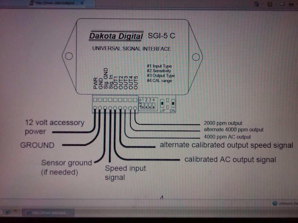
Connect the power and ground wires to the speedometer converter interface.The yellow/blue wire comming from the dash needs to be run into the input of the converter and the wire leading to the cluster needs to be run into output 1, use only output one as this is the only output that will generate the proper nissan signal.
If you connected everything properly when you reinstall the cluster it is best to keep the converter exposed for calibration and for testing.
Adjustment of the unit goes as follows:old differental final/new differential final = calibration ratio
If the calibration ratio is greater than one you need to switch dipswitch 4 to 'on', if it is less than one it needs to be set 'off'All other switches should be switched off unless calibration ratio dictates on.Using the calibration tables included in the unit's instructions set the converter using the 'cal coarse and cal fine' tables...for the q45 final drive cal coarse and fine settings are 3 and 3 respectively (calibration ratio is 1.159 unit has a setting for 1.1585).
It is best to verify via gps or radar to ensure the converter is set properly else it can possibly be worse than it was than you started with.
Installed harness connections:
Overall assembly:
Installed product:
Hope this helps!

How-To: Speedometer conversion using dakota digital sgi-5 converter box
-
ninety1two40

- Posts: 261
- Joined: Mon Apr 02, 2007 2:39 pm
- Car: 1991 240sx SE
- Contact:
Re: How-To: Speedometer conversion using dakota digital sg ... (Carl H)
Bump to the top for newbs.
I've had this working on my RB25 swapped S13 for a couple years now, it works great with my HUD.
I've had this working on my RB25 swapped S13 for a couple years now, it works great with my HUD.
-
mexicanracer03

- Posts: 563
- Joined: Thu Nov 09, 2006 12:57 pm
- Car: 95 S15FRONTEND SR20DET and 97 2JZ GT4294/ 93 SC300 Black/ 95 SC300 Green
Re: How-To: Speedometer conversion using dakota digital sg ... (Carl H)
I've got this in my s142jz for the Tach, and spedo love this little box.
Re: How-To: Speedometer conversion using dakota digital sg ... (Carl H)
I have a similar problem and I was wondering if you can please tell meWhat I can to correct it.I have a 1989 Nissan 240SX with a engine swap of 1994 KA24DE and 1992Automatic transmission. My Speedometer was not even working until we replaced a Capaciator on it from this link:
http://www.nicoclub.com/archiv....html
It fixed the cluster but then the speed was off and was reading higher than the speed Of the car by 10MPH and now the speedometer is off by 30 MPH higher and I am wondering if the dakota digital sgi-5 conveter boxWould solve the issue?
http://www.nicoclub.com/archiv....html
It fixed the cluster but then the speed was off and was reading higher than the speed Of the car by 10MPH and now the speedometer is off by 30 MPH higher and I am wondering if the dakota digital sgi-5 conveter boxWould solve the issue?
-
ghost_22_47

- Posts: 353
- Joined: Fri Dec 11, 2009 4:09 pm
- Car: 1993 Nissan 240sx Covertible with RB26dett
2004 Audi A4 1.8T Quattro
Re: How-To: Speedometer conversion using dakota digital sgi-
I'm trying to wire my speed signal to my ECU for Nistune (dont really need it, just want to do it)
Can I use Output #2? or do I have to peel back some of the Output one wire and tie in a wire to run to the ECU Speed pin?
Can I use Output #2? or do I have to peel back some of the Output one wire and tie in a wire to run to the ECU Speed pin?
Re: How-To: Speedometer conversion using dakota digital sgi-
Anyone know what i would have to set this to for an rb25det in an s13 with a stock rear and stock rims??
Find Your Forum!