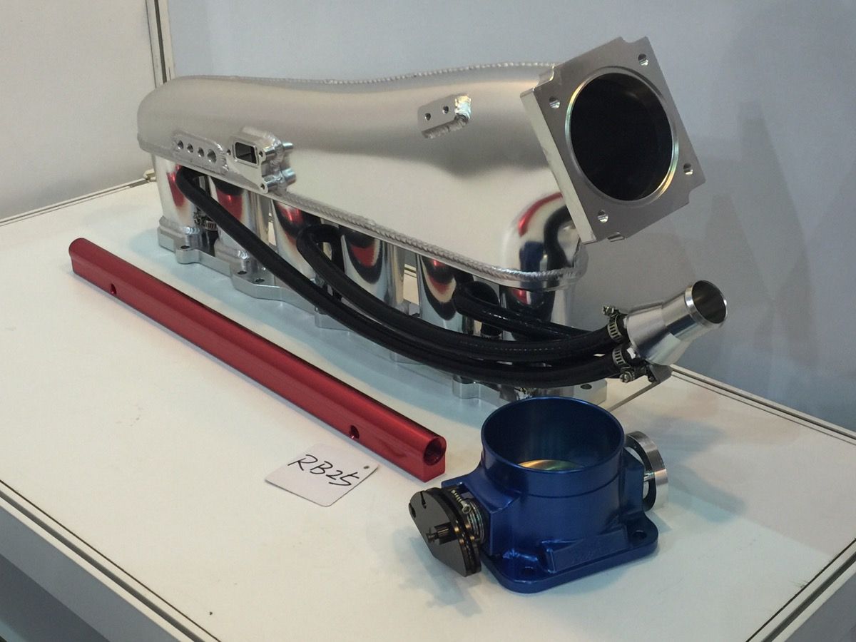
Having a bit of trouble determining how coolant lines need to be routed. I have the Otaku Garage intake manifold for my RB25DET NEO, I have eliminated the coolant oil cooler, and the lines on the intake come straight from the head valley (IE no coolant crossover like factory intake and greedy intake).
Questions:
Do the coolant valleys in the head connect to each other inside the head? Thus no need for the crossover tube?
Since I eliminated the oil cooler, can I just cap the lines? I see no need to connect them since it's a straight shot back to the thermostat.
Also, I am running the NEO AAC/IAC; Which I believe requires coolant...which plugs for coolant, and which for vaccum?
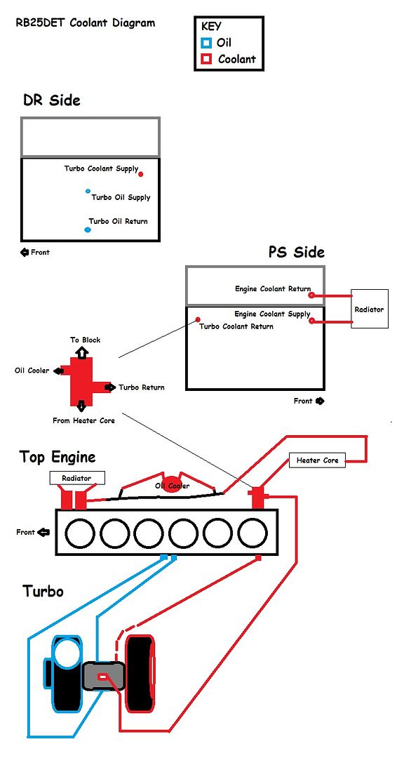
I'm looking for a diagram like this:

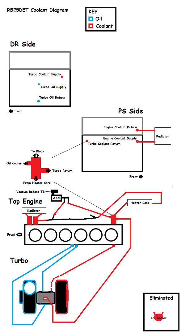
My Setup
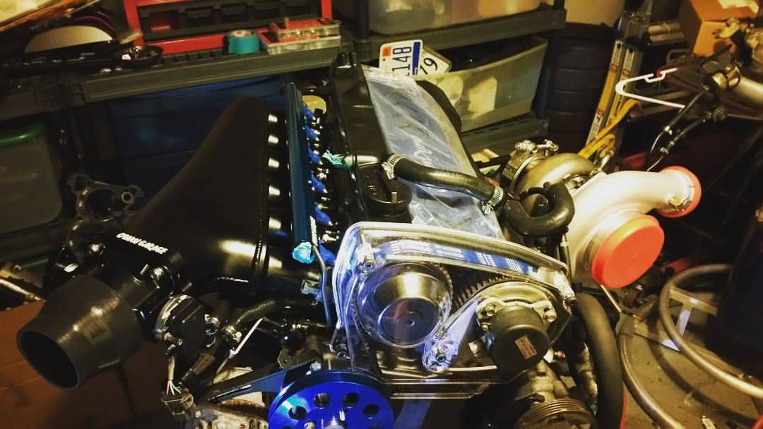
Picture of intake coolant lines
RB25det NEO AAC/IAC: