Basic Theory of Operation The amount of fuel and air sucked/forced into a cylinder is dictated by several factors, one of which is charge velocity. Higher velocity means more gets in. At low RPMs, you usually aren't generating much boost, and since you don't have much displacement, you're not sucking much either. A larger opening lets the charge in slower, a smaller one faster. Think of a garden hose: just holding the hose out, the water comes out at a decent rate, but it's in no real hurry. Press your thumb over the opening to restrict the exit area, and flow velocity must increase, for flow to be maintained. At some point, you are restricting total theoretical flow, but at lower flow levels, this will cause a higher exit velocity. The same is true with the CA18DET's secondary butterfly system. At lower airflow points (i.e. RPM), the butterflies are closed, forcing nearly all intake charge to go through half the space, increasing its velocity into the cylinder and therefore the rate at which the cylinder fills. More charge = more power, all else being equal.
CA18DET Secondary Butterflies Control System The secondary butterflies are controlled via a vacuum operated actuator, that sits on the back end of the intake manifold. When there is a vacuum, the butterflies are closed, and when there is no vacuum, are allowed to open. When correctly hooked up, this is controlled via the ECU for (presumably) optimal operation. The stock system uses a fairly complicated arrangement of gizmos, which I will cover towards the end. There are many ways to hook up this system. I'll start with the simplest.
Method 0: Do Nothing (WRONG way) This is the worst method, i.e. not hooking it up at all. You get no benefits at all, and potentially some losses vs. not having the butterflies at all.
Method 1: The Simple way This is the bare minimum anyone should do, and is very straightforward. Basically, you connect it to the intake manifold such that it sees vacuum and boost directly. As described above, when there's vacuum it'll pull the butterflies closed, and when there's no vacuum or boost, it'll let them open. This is not necessarily optimal, and from multiple accounts, is nowhere near as good as the correct way of hooking it up. You can either dedicate one of the vacuum ports to this, or T it in with something else (i.e. the FPR).
Method 2: The Stock ("Correct") Way This is how it should be done, if you're running a stock ECU. By stock I mean OEM type engine control, retuned ECUs inclusive. This is quite complicated. The ECU controls the butterflies by turning a solenoid on and off. When on, they close, and when off, they open. This is achieved by connecting (when on) the butterflies to a vacuum source, and then when off, connecting them to a vent to ambient air pressure.
In detail, the vacuum source comes off the intake manifold, goes through a vacuum delay valve (possibly check valve), into a vacuum tank, then to the solenoid, then another vacuum delay valve (they’re to smooth the on/off transition) and finally into the actuator. The solenoid also has a connection running around to the intake side of the engine, behind the MAF, before the turbo, where it "dumps" the vacuum when the butterflies are switched off. The first valve may be a check valve (makes more sense), but the parts catalog in all regions has it listed "delay", whilst the FSM says "check" - and "check" also for the other valve, which can't be right or it would never release the actuator! Use the OEM parts and you won't have to care.
What happens is that due to the vacuum check valve built into the vacuum tank, the engine is always pulling a vacuum, or at least, not "venting" the vacuum, from the vacuum tank. This keeps it ready to go, all the time, in theory. After the tank, we have the solenoid. This is the one the ECU controls. When the solenoid is on, the butterflies are continuously held in vacuum by the vacuum tank. When off, the solenoid shunts the vacuum in the actuator and it's vacuum hose to the ambient air pressure by the intake, which releases the vacuum and opens the butterflies. Between the manifold and the vacuum tank, and also between the actuator and the solenoid, are vacuum delay valves. You could live without the valves, they’re just there to smooth things out. They merely restrict airflow to make the pressure changes in the system less sudden..
Like I said, it's complicated. It also takes up a lot of space in the engine bay...
Here are some images showing the layout/connections, and how the solenoid operates. You can find the entire section 223 image in original form here, however it is not nicely colorized and quite hard to read. I have also blanked out all the unrelated bits in the section for the purposes of this discussion. Diagram of the stock layout and connections (if your browser (ex. Firefox) squishes it to fit the forum, right click and 'View Image' to make it legible):
A note on above image: The uncolorized stuff in the bottom right with another solenoid and a few hoses I left in as it is connected to the same ambient source, but not highlighted as it is unrelated. This is the stock boost control system, when ECU sees more airflow than it thinks is ok it switches the solenoid to allow wastegate to see real boost, otherwise it sees the ambient pressure in that little cap.
Solenoid energized (on), secondary butterflies closed:

As you can see, it is connecting the butterfly system to the vacuum tank, which provides a vacuum source to pull them closed.
Solenoid de-energized (off), secondary butterflies open:
And here they are instead connected to the ambient air source, allowing them to open as they are no longer pulled closed.
Technical Details: - Part number for solenoid is 14956-35F10 (JDM CA18DET) or 14956-27M00 (USDM CA18DE); partcodes of 14956VA and 14956U respectively - Part number for vacuum tank is 22372-V6700; in the diagrams partcode is 27085Y (both JDM CA18DET and USDM CA18DE) - Part number for delay valve, to manifold, is 14958-H9910; in the diagrams partcode is 14958QA (JDM CA18DET) or 14958M (USDM CA18DE) - Part number for delay valve, to actuator, is 14958-V6700; in the diagrams partcode is 14958Q (both JDM CA18DET and USDM CA18DE) - Solenoid is ground switched by ECU, pin 8 on the ECU. This means one wire to pin 8 on ECU and one to power (12V). - Vacuum tank and both delay valves can be had from CA18DE equipped Pulsars. - Both the above listed JDM CA18DET and US CA18DE solenoids are functionally identical, but are slightly different due to dimensions and mounting, hence different part numbers. Any solenoid will work as long as you connect it properly and it has 3 ports, A, B, Common, in a configuration such that when de-energized ports A and Common are connected, and when energized B and Common are connected. physical positioning of ports does not matter.
*NEW* 04/04/2008Method 3: Cutting out the middle men
Quite a few Volvo, Volkswagon, etc cars from the mid to early '90's had a vacuum operated cruise control system. With this system, they had a vacuum pump with built in release solenoid. I have just slapped one of these in, and it awesomely simplifies things without sacrificing anything.
They look like this:
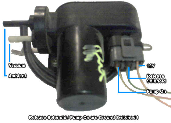
I pulled this one off a Volvo wagon of some sort, didn't think to check what model. If you see that it has cruise control, follow the second throttle cable to the diaphragm, and from there follow the vacuum tube and you'll find this puppy.
As I have noted in the image above, there's three wires on their harness connection, which are for 12V, ground switched release solenoid, and ground switched pump engagement.
Connecting this in lieu of the standard junk isn't too difficult. You'll need to slap a SPDT relay inbetween the ECU and the pump as follows:
SPDT Relay:Terminal 85 (or 86) - Switched 12V from engine harnessTerminal 86 (or 85) - ECU butterfly control switched groundTerminal 30 - GroundTerminal 87 - Release SolenoidTerminal 87a - Pump On
Vacuum Pump:12V input - Switched 12V from engine harnessRelease Solenoid
Note that for relay terminals 85 & 86, the orientation 12V vs ECU doesn't matter unless your relay wiring includes a protection diode, which you don't really need anyways since the ECU is built to drive a solenoid with that wire anyways. If you do have a diode (for example, bought a relay boss with it built in) then make sure whichever side of the coil / diode that has the line on it marking the cathode is connected to the switched 12V, and the other side is connected to the ECU.
Finally, run your vacuum line from your pump (white connection, black is the atmospheric vent) to your butterfly actuator (via delay valve if you wish to keep the OEM smoothness). Now cap off or remove all the vestigial bits from however you had it setup before.
I'd have to say now method 3 is the way to go, it is both very simple to setup and very functional.
(NOTE: SEE PAGE 3 W/A POST BY BUDDY WORM FOR UPDATES ON WIRING FOR THIS METHOD)
Alternative Methods If using some form of standalone or other gizmo letting you use MAP instead of MAF sensing, you could modify the "correct" method where it would normally dump the vacuum through the solenoid to the intake post-MAF, pre-turbo piping. You could just let this vent out (might want to put a small filter on it) instead, since the MAP will cover for any variances due to the "leak" effect. This will at least remove one run of vacuum connections.
Another possibility (one which I've toyed with "on paper" but haven't had the time/energy to pursue) is replacing the actuator with a servo or stepper motor, which is then controlled via a microcontroller of some kind. Many variations on this theme could be done, such as merely full open/close in response to an on/off switch a la stock ECU, or precise degree open/close controlled via a standalone. One would presumably install limit switches and something that rotates with the rod driving the butterflies to trigger them, so that you can shut down the motor when you hit full open/close, rather than keep sinking current into it for no purpose at all.
Keywords: butterflies butterfly secondary secondaries vacuum check delay boost valve actuator
Modified by biosehnsucht at 6:30 PM 4/4/2008