This article covers the process of replacing the Nissan 720 pickup ball joints, from start to finish - Enjoy, and if you have any questions, feel free to ask them here in the thread!
720 Ball Joint Replacement DIY Article
Thanks!
720 Ball Joint Replacement Thread
-
fastboatman29212
- Posts: 493
- Joined: Sun Jul 25, 2010 6:45 pm
- Car: left this forum. Sold my truck.
- Location: South Carolina
720 Ball Joint Replacement Thread
Last edited by fastboatman29212 on Fri Aug 16, 2013 7:38 pm, edited 5 times in total.
-
Steveka24det
- Posts: 114
- Joined: Sun May 31, 2009 10:13 am
- Car: 240sx 91
Re: 720 Ball Joint Replacment Thread
wow very nice write up 
Re: 720 Ball Joint Replacment Thread
Great write up! Will consult this when I need to do this myself...
Only suggestion I would make is to replace the torsion rod bushings since the rods need to be removed anyway. Having access to the two bolts while the ball joints are out would make it that much easier.
Only suggestion I would make is to replace the torsion rod bushings since the rods need to be removed anyway. Having access to the two bolts while the ball joints are out would make it that much easier.
-
fastboatman29212
- Posts: 493
- Joined: Sun Jul 25, 2010 6:45 pm
- Car: left this forum. Sold my truck.
- Location: South Carolina
Re: 720 Ball Joint Replacment Thread
I think you mean the Tension Rods, right? They go from the front of the frame to the lower control arm at an angle and have bushings where they bolt to the frame.86 720 wrote:Only suggestion I would make is to replace the torsion rod bushings since the rods need to be removed anyway. Having access to the two bolts while the ball joints are out would make it that much easier.
You are correct, but I tried to keep the post from wandering into other issues like sway bar, shocks, bearings, etc. They all would be more accessible "while you are there". I'll let people decide what else they want to do at the time they do the ball joints.
Re: 720 Ball Joint Replacment Thread
I've noticed that there are several names for the rod, my book says torsion rod, I have another book that reads compression rod!fastboatman29212 wrote:I think you mean the Tension Rods, right? They go from the front of the frame to the lower control arm at an angle and have bushings where they bolt to the frame.86 720 wrote:Only suggestion I would make is to replace the torsion rod bushings since the rods need to be removed anyway. Having access to the two bolts while the ball joints are out would make it that much easier.
You are correct, but I tried to keep the post from wandering into other issues like sway bar, shocks, bearings, etc. They all would be more accessible "while you are there". I'll let people decide what else they want to do at the time they do the ball joints.

Re: 720 Ball Joint Replacment Thread
Great write up & pictures. How about a write up on lowering, re-indexing 520 & 521 torsion bars. They are different then the 620 & 720 set ups.
-
fastboatman29212
- Posts: 493
- Joined: Sun Jul 25, 2010 6:45 pm
- Car: left this forum. Sold my truck.
- Location: South Carolina
Re: 720 Ball Joint Replacment Thread
I'll leave the 620 threads to be done by people who own them. I really don't know anything about them so I certainly can't post stuff about them.
-
breadbox

- Posts: 8549
- Joined: Tue Oct 17, 2006 4:09 pm
- Car: 89 Nissan 240SX
89 Koop
84 720 4x4KC - Location: Va Bch
Re: 720 Ball Joint Replacment Thread
Nice Write up. Got any part numbers you wanna put up here?
-
fastboatman29212
- Posts: 493
- Joined: Sun Jul 25, 2010 6:45 pm
- Car: left this forum. Sold my truck.
- Location: South Carolina
Re: 720 Ball Joint Replacment Thread
the link below should work. They are the same ones I installed. They are on sale again!!!
That's CRAZY CHEAP!!! Only $39.43 for all 4 ball joints delivered!
http://cgi.ebay.com/ebaymotors/2-Lower- ... odel%3A720
That's CRAZY CHEAP!!! Only $39.43 for all 4 ball joints delivered!
http://cgi.ebay.com/ebaymotors/2-Lower- ... odel%3A720
Last edited by fastboatman29212 on Thu Aug 26, 2010 5:37 pm, edited 1 time in total.
Re: 720 Ball Joint Replacment Thread
Great point Breadbox.
-
fastboatman29212
- Posts: 493
- Joined: Sun Jul 25, 2010 6:45 pm
- Car: left this forum. Sold my truck.
- Location: South Carolina
Re: 720 Ball Joint Replacment Thread
OK, check one of my posts earlier for the Link to eBay for the ball joints. On second thought, here it is again.
http://cgi.ebay.com/ebaymotors/2-Lower- ... odel%3A720
http://cgi.ebay.com/ebaymotors/2-Lower- ... odel%3A720
-
breadbox
- Posts: 8549
- Joined: Tue Oct 17, 2006 4:09 pm
- Car: 89 Nissan 240SX
89 Koop
84 720 4x4KC - Location: Va Bch
Re: 720 Ball Joint Replacment Thread
also the knuckle on 4WD is a bit different. so from illustrations the lower ball joint could be the same. but IDK for sure.
-
fastboatman29212
- Posts: 493
- Joined: Sun Jul 25, 2010 6:45 pm
- Car: left this forum. Sold my truck.
- Location: South Carolina
Re: 720 Ball Joint Replacment Thread
If you check their eBay store, I think they have ball joints for 4WD too.
Re: 720 Ball Joint Replacement Thread
I bought a set of those for my sons 85 720 4x4... great deal considering the local AutoZone wants $120 for all 4.
They're the same for 2wd and 4wd...
They're the same for 2wd and 4wd...
-
Rev_D21

- Posts: 5946
- Joined: Sun Jan 12, 2003 9:49 pm
- Car: 1986.5 D21 LB HD 2WD V6 5Speed
1991 D21 Reg 2WD Auto
1995 D21 Reg 2WD 5Spd
1996 D21 Reg 4WD 5Spd
2012 Versa 1.6S 5-Speed - Location: Somwhere in Western NY
- Contact:
Re: 720 Ball Joint Replacement Thread
Excellent write-up!
-
NorskeMann82
- Posts: 12
- Joined: Thu Sep 23, 2010 12:34 am
- Car: 1986 Nissan 720 King Cab
- Location: Meeker, OK
Re: 720 Ball Joint Replacement Thread
I wish this was available when I did the upper and lower ball joints on mine. That was a pain in the rear. Having my father-in-law "helping" wasn't that great either. Even when I was doing things right, I was wrong. LOL
-
flinterman2000
- Posts: 1011
- Joined: Mon May 04, 2009 5:32 pm
- Car: 2000 Nissan Wingroad, 85 Datsun 720 Pick Up.
Re: 720 Ball Joint Replacement Thread
Great Idea. This write up is way better than the one I did for the changing of the tail light lens. Thanks Breadbox for separating the typing. Lets all help by doing a write up in one form or the other. 
-
brianzero

- Posts: 53
- Joined: Wed Feb 03, 2010 6:43 am
- Car: 1986 Nissan 720 4x4 Regular Cab 265,000 mi! (Gasser unfortunately)
Re: 720 Ball Joint Replacement Thread
I just bought all 4 ball joints for $80. I should do the 4x4 balljoint DIY. There are some extra things to remove, like the front axles...
-
fastboatman29212
- Posts: 493
- Joined: Sun Jul 25, 2010 6:45 pm
- Car: left this forum. Sold my truck.
- Location: South Carolina
Re: 720 Ball Joint Replacement Thread
That would be a great resource for anyone with a 4 X 4. I'll look forward to seeing your post.
Re: 720 Ball Joint Replacement Thread
Sick Slides for the Ball Joint Replacement!!...Respect to your for doing it on your own and learning it...I'm going to do mine soon.
Just purchased an 1984 720 SingleCab Long Bed out here in Vegas
I LOVE it so much already....Love hitting the Pick a part and fixing things here and there.
Just got new tires today 205 65R15's drives sooo much smoother

Just purchased an 1984 720 SingleCab Long Bed out here in Vegas
I LOVE it so much already....Love hitting the Pick a part and fixing things here and there.
Just got new tires today 205 65R15's drives sooo much smoother
-
pistolkeith
- Posts: 50
- Joined: Sun Sep 18, 2011 11:36 pm
- Car: 1985 Nissan King Cab 720
Re: 720 Ball Joint Replacement Thread
Dear Fastboatman, in order to replace the shocks in the front, i need to remove the hub from the upper and lower control arm right?
-
fastboatman29212
- Posts: 493
- Joined: Sun Jul 25, 2010 6:45 pm
- Car: left this forum. Sold my truck.
- Location: South Carolina
Re: 720 Ball Joint Replacement Thread
Sorry, to say, but I really don't know
Sorry, but I really don't know the answer. I would think you could replace the shocks WITHOUT removing the hub, but I've never done it. Let us know what you end up doing.pistolkeith wrote:Dear Fastboatman, in order to replace the shocks in the front, i need to remove the hub from the upper and lower control arm right?
-
pistolkeith
- Posts: 50
- Joined: Sun Sep 18, 2011 11:36 pm
- Car: 1985 Nissan King Cab 720
Re: 720 Ball Joint Replacement Thread
if i jack it up and remove all load off the hub, that removes all load from the shock absorber right? i saw a video on youbtube of a gentleman replacing his 93 Toyota pickup and he still had his hub on. he undid the top bolt and them the bottom and it just slid out. i assum that would be the same. ill give it a look and see how i go 
-
fastboatman29212
- Posts: 493
- Joined: Sun Jul 25, 2010 6:45 pm
- Car: left this forum. Sold my truck.
- Location: South Carolina
Re: 720 Ball Joint Replacement Thread
That should work.pistolkeith wrote:if i jack it up and remove all load off the hub, that removes all load from the shock absorber right? i saw a video on youbtube of a gentleman replacing his 93 Toyota pickup and he still had his hub on. he undid the top bolt and them the bottom and it just slid out. i assum that would be the same. ill give it a look and see how i go
-
jackspade21
- Posts: 15
- Joined: Wed Jun 15, 2011 11:27 am
- Car: 85 Nissan 720 2.4L automatic
Re: 720 Ball Joint Replacement Thread
So I am just finishing up this very procedure on my truck, but didn't have the forethought to leave one bolt in between the lower arm/ball joint and the tension rod. Now the holes through the tension rod-lower arm-lower ball joint are off by about 1/4". Any advice on getting them lined back up? I am considering using a long bar clamp to pull the lower control arm toward the front of the vehicle. Any thoughts?
BTW, very nice write-up! It was a great help!
BTW, very nice write-up! It was a great help!
-
fastboatman29212
- Posts: 493
- Joined: Sun Jul 25, 2010 6:45 pm
- Car: left this forum. Sold my truck.
- Location: South Carolina
Re: 720 Ball Joint Replacement Thread
It will be extra work, but less frustrating to undo the lower ball joint installation and get things lined up properly. That would be better than stripping threads or twisting off a bolt head.
-
valentine.markd
- Posts: 7
- Joined: Mon Dec 10, 2012 9:35 am
- Car: 84 Nissan 720 2.4 4x4
215K - Location: Colorado
Re: 720 Ball Joint Replacement Thread
I will be attempting this repair on both upper and lower ball joints on both sides tonight. Thanks for the write up and I will let you know how it goes.
-
valentine.markd
- Posts: 7
- Joined: Mon Dec 10, 2012 9:35 am
- Car: 84 Nissan 720 2.4 4x4
215K - Location: Colorado
Re: 720 Ball Joint Replacement Thread
I was able to do the upper ball joints on both sides of my 720 4x4 last night and replace the shocks! The truck rides like new.
The uppers were about the same as noted above. The difference is that there is an axle in the way so the working space is limited. Here are a couple before pictures.
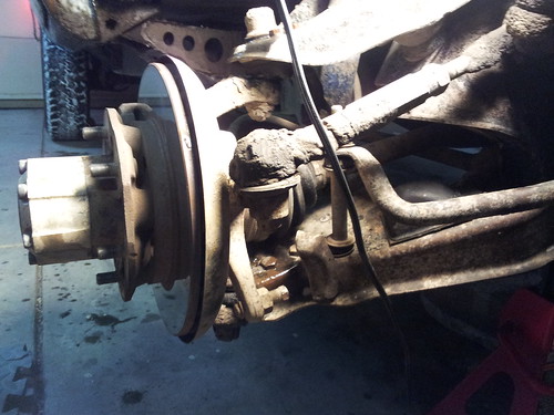
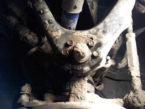
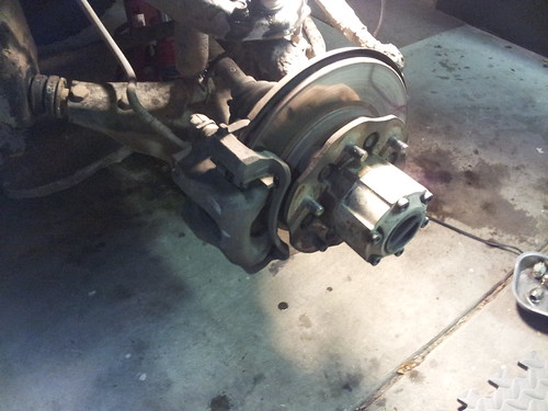
The bottom ball joints are going to be a bit different. There is no tension rod connected to the bottom but I do have to remove the torsion bar.
I will post some pictures when I get to replacing the bottom joints.
The uppers were about the same as noted above. The difference is that there is an axle in the way so the working space is limited. Here are a couple before pictures.
The bottom ball joints are going to be a bit different. There is no tension rod connected to the bottom but I do have to remove the torsion bar.
I will post some pictures when I get to replacing the bottom joints.
-
AZhitman

- Administrator
- Posts: 54548
- Joined: Mon Apr 29, 2002 2:04 am
- Car: 58 L210, 63 Bluebird RHD, 64 NL320, 65 SPL310, 66 411 RHD, 67 WRL411, 68 510 SR20, 75 280Z RB25, 77 620 SR20, 79 B310, 90 Z32, 91 GTi-R, 92 Silvia Qs, 98 S14, 23 Z.
- Location: Surprise, Arizona
- Contact:
Re: 720 Ball Joint Replacement Thread
UPDATE: Thanks to fastboatman, all of the pictures are now permanently hosted and archived forevermore!
Check the first post in this thread for the article, and feel free to bookmark it, share it, and ask any questions here...
Oh, and how about a huge "THANK YOU" to fastboatman for such a great DIY! 

Check the first post in this thread for the article, and feel free to bookmark it, share it, and ask any questions here...
Oh, and how about a huge "THANK YOU" to fastboatman for such a great DIY!
Re: 720 Ball Joint Replacement Thread
Does anyone know what size socket it takes to remove lower ball joint castle nut? That is the only tool that i am missing from getting this done, and I do not want to purchase random sockets. Thank you in advance!