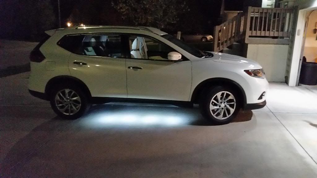
For the parts that I am missing pictures for, I would love if anyone who does this install to send me pictures and I will be more than happy to add them. Also any tip or tricks you find when doing the install, i would be happy to add as well.
Copy of the Nissan Tech instructions can be seen here:
https://www.nissan-techinfo.com/asistgc ... C1UG10.PDF
Parts Needed:
2x - 999Q9-AY001 (Driver and Passenger)
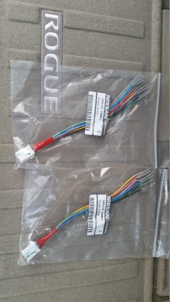
1x - 999F4-AX010 (External ground lighting kit)
Starting on Passenger side. Remove trims pieces. All you have to do is pull up, not too hard but enough.
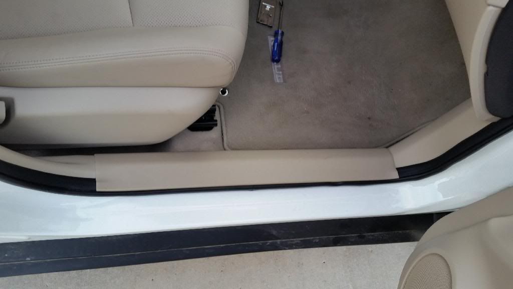
There is a plastic nut that needs to be removed. Should be able to unscrew it with you hand. There is also a green clip, which will take a little bit of pulling force to undo. You will have to pull the black rubber molding to remove kick panel. Third pictures show everything removed
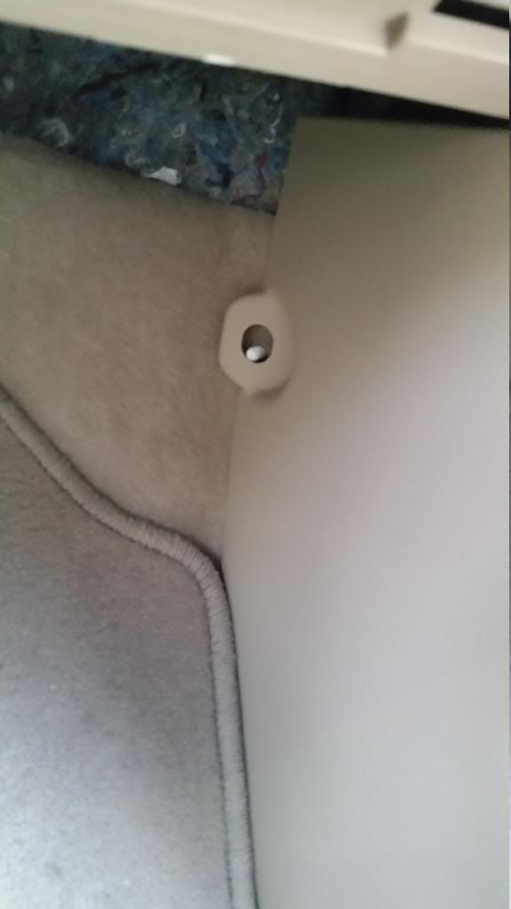
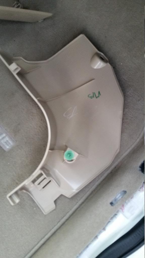
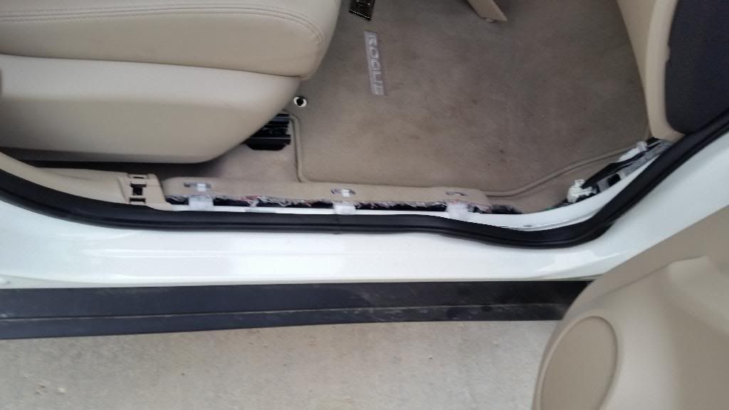
The following is the wiring you will see behind the kick panel. The plug you need is taped up and away as shown in the second picture (I had already removed the tape when pictures was shown. They used black electrical tape.)
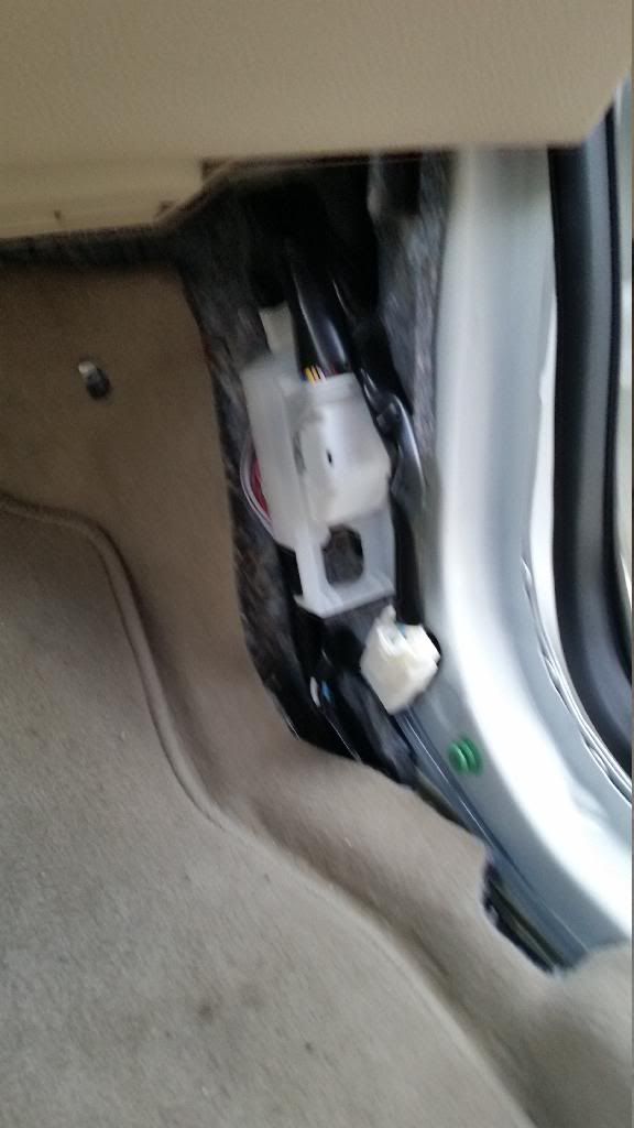
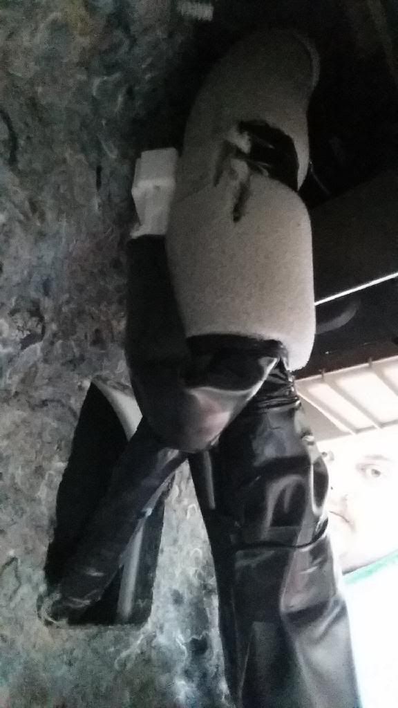
Next remove all of the screws (10 mm or Phillips screwdriver) which hold the mud guard trim. There are also 2 screws in the wheel well which will need to be removed or remove mud flaps if equipped. I believe there are about 7 or 8 screws, the guard will not fall off since there are black clips to hold it on as well.
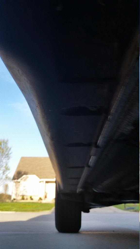
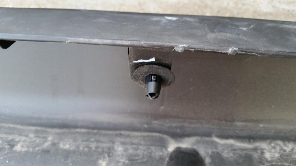
Now for the scariest part of the whole install. Removing the guard completely, the trick to this is to grab the bottom there is meets the pinch weld and pull towards you. It’s going to take a good amount of pulling force and pop it off. I actually broke 2 clips on driver side and 3 on passenger side in the process. It seems no matter how you do this part you’re going to break at least one clip. The good news is that if you do break some of them there are enough that it’s not loose without them a few of them.
(Picture of clip)
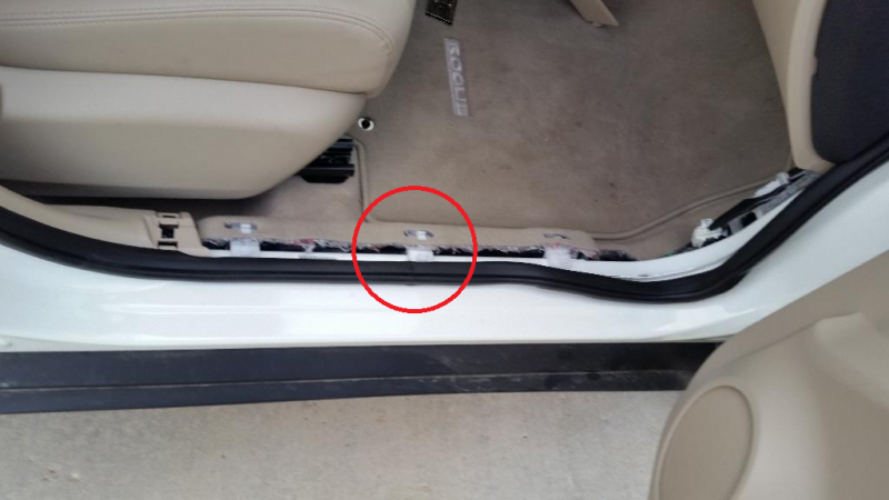
I don’t have pictures of this part but there is a round tape disc under the harness near the 2nd white clip (red circle in picture). You will have to pull the carpet back a little bit to get your hand in there. You will need to pull that off. The wiring will be running thru this hole.
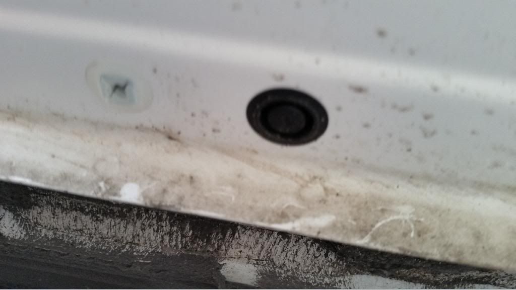
Underneath the car along the rocker panel, there will be a plastic stopper. It will be the same distance back from the front of the car as the one inside under the carpet. I used a trim removal tool to pop it off, you can use a flat tip screwdriver too.
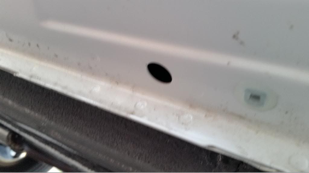
For this next few parts I don’t have any pictures as they got deleted. Hopefully the next person who does this can get some pictures and I can update this with them. You will need to clean the inside and outside of the mud guard. I used Windex and a microfiber towel. Once you have clean it real good, you are now ready to put the drill guide (See next step below doing so).
Passenger mud guard
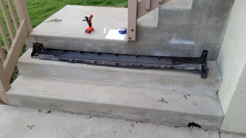
Now you need to measure 11.75” (inches) from the second screw. It’s about where the red circle is. Picture below has more details.
Passenger side
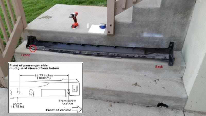

Once you have the drill guide on drill your 4 holes using a 1/2” (inch) drill bit. Once you drilled your holes, clean off any stray pieces of plastic. Flip over the guard and clean inside around the holes with the supplied alcohol wipes. This area should be pretty clean already since you wiped it down in a previous step to get most of the dirt and dust cleaned out. You should have gotten 4 wipes. I did 2 holes per wipe.
While the mud guard is drying peel the corners back on the foam tape. This part is a pain because the red backing didn’t want to come off. My ol’lady had good luck since she has nails to pick at them. Once you have the red backing peeled a little the mud guard should be dry. Take the end LED and start from the back and work your way to the front. The LED should go in the hole and be just about flush on the other side. Apply some pressure to ensure they stick and continue to the next one.
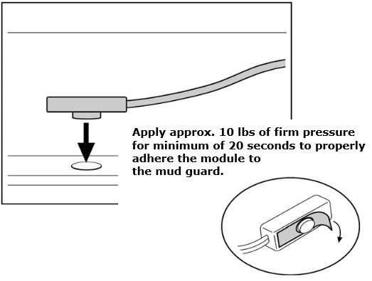
Once all your LEDs are attached, take one of the rubber grommets and feed the wires thru it (make sure they are put on backwards, see pic below). Next take the Flex Tubing and thread the wires thru it. Now, take the red and black wires from the LEDs and zip tie them together with the 11” (inches) zip tie. Stick the other end in the hole in the rocker panel and fish the wires into the car. Last feed the second grommet on, so you should have one grommet on the outside and one inside.
Slide the outside grommet over the flex tubing and push the tubing thru the holes so it sticks out inside the car. Slide the inside grommet over the flex tubing. Secure the outside rubber grommet to the hole under the car. Make sure the flex tubing it sticking out about 2” (inches).
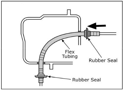
Reattach the mud guard by just the clips. Pull the wires snug (don’t not pull tight, need to leave some slack). The best way I found to do this step is to hold the mud guard close and pull the wires at the same time to see how much is left.
Now, it’s time for wiring!
Passenger side is going to have a control module and the red and black from the LEDs connecting to the Accessory connector (see below).
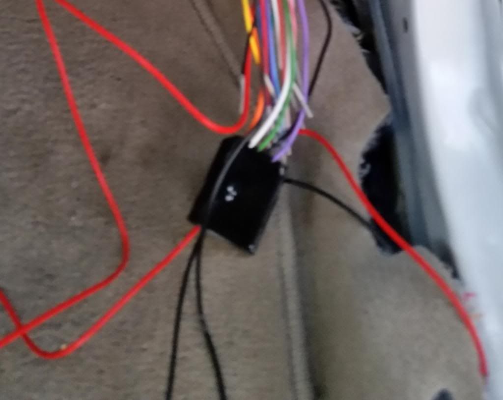
Passenger Side Connections
Make the following connections for the Control Module to the Accessory Connector:
- Black wire from the Control Module to the Black wire on the Accessory Connector
- Purple wire from the Control Module to the Pink wire on the Accessory Connector
- Green wire from the Control Module to the White wire on the Accessory Connector
- White wire from the Control Module to the Yellow wire on the Accessory Connector
- Orange wire from the Control Module to the Grey wire on the Accessory Connector
Make the following connections for the LEDs to the Control Module:
- Black wire from LEDs to the Black wire on the Control Module
- Red wire from the LEDs to the Orange wire on the Control Module
Should end up with a mess like this:
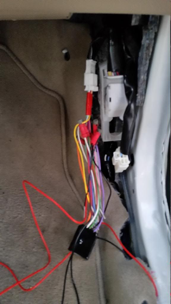
Driver Side connections
Make the following connections for the Control Module to the Accessory Connector:
- Black wire from the LEDs to the Black wire on the Accessory Connector
- Red wire from the LEDs to the Grey wire on the Accessory Connector
Plug the Accessory Connector into the plug you untaped and the LEDs should power on with one of the doors open. You may have to close and open the door depending on how long you have had the door open. Now all you have to do is clean up the wiring. I used 2 small zip ties. Re-install trims pieces and start over for the driver side. Repeat steps for driver side. Stand back and hit the unlock button, give yourself a fist pump
