(Pretty sure it was p1132...but, will check and update if diff.)
CORRECTED: P1320 was the code NOT P1132
Daughter's SES light has been coming on and going off....Took it to Nissan and they said it was definitely a coil pack, but could not pin point which one. THey said that Nissan advises to replace ALL in cases like this.
I have been turning the light off and it stays off for 100 - 300 miles.
Sometimes, when the car is cranked it starts REALLY rough and idles rough. Light will come on.
If you turn it off and then try again, it acts fine. Runs strong, no pinging, no skipping.
Any suggestions, other than replacing ALL packs???
Modified by SVTCOBRA at 12:14 PM 1/9/2010

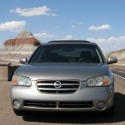
2000 Max SE w/87K miles P1132 code
Re: 2000 Max SE w/87K miles P1132 code (SVTCOBRA)
About the only thing you can do is to unplug each coil and see if unplugging one does not change how the engine runs. You can also ohm the coils to see if any are out of the normal range.
-
SVTCOBRA

- Posts: 6052
- Joined: Wed Sep 03, 2003 2:26 am
- Car: 2018 Q60 AWD 2023 F150 4x4 5.0 FX4
- Location: LKN NC
Re: 2000 Max SE w/87K miles P1132 code (maxhopper97)
If I can catch it (daughter's car) idling rough after a rough start, that might work! But, otherwise it runs smooth. Will check with my full time mechanic buds (i only play one on TV) on checking the coils.maxhopper97 wrote:About the only thing you can do is to unplug each coil and see if unplugging one does not change how the engine runs. You can also ohm the coils to see if any are out of the normal range.
Thanks!
-
NutriaforBreakfast
- Posts: 1316
- Joined: Wed Sep 26, 2007 1:41 pm
- Car: Nissan Maxima 1995 VQDE engine
Re: 2000 Max SE w/87K miles P1132 code (SVTCOBRA)
Use a multimeter to check the resistance of the coil packsMake sure the coil pack is receiving the correct voltageMake sure the coil pack is not torn or damanged
-
gwoods
- Posts: 3896
- Joined: Fri Jul 27, 2007 11:57 am
- Car: 2013 Infiniti M37x
1999 Nissan Altima SE limited 5spd
1992 Miata (soon to be turbo)
1965 Cj-5 with 327 v8
2012 Toyota Sequoia Limited - Location: Phoenix
Re: 2000 Max SE w/87K miles P1132 code (SVTCOBRA)
I would buy 1 coil pack and start moving it from coil pack to coil pack until you find the bad apple. That my friend is the only way. If it is only intermitenly failing your going to have a tough time finding it using a multimeter or any other tool
-
zozoka1212

- Posts: 5533
- Joined: Wed Mar 14, 2007 7:54 pm
- Car: 08 Infiniti G35x
- Location: Winter wonderland
Re: 2000 Max SE w/87K miles P1132 code (gwoods)
+1gwoods wrote:I would buy 1 coil pack and start moving it from coil pack to coil pack until you find the bad apple. That my friend is the only way. If it is only intermitenly failing your going to have a tough time finding it using a multimeter or any other tool
-
loystock
- Moderator
- Posts: 2144
- Joined: Sun Sep 21, 2003 9:12 pm
- Car: 10 Pilot, 97&03 Q45s, 97 I30 and 06 M35 Sports (04 G35 & 99 I30-RIP)
- Location: San Jose, CA
Re: 2000 Max SE w/87K miles P1132 code (SVTCOBRA)
If it is an Ignition problem, then the code cannot be P1132 since it will not conform with the OBD II fault coding. A Diagnostic Trouble Code (DTC) has 5 digits – XABCD where: -X is for the System Code (P=Powertrain; B=Body; C=Chassis; U=Network)-A is for the Code Type (0=Generic; 1=Specific to Manufacturer)-B is for the Sub-System Code (1&2= Fuel and Air Metering; 3=Ignition and Misfire; 4=Aux Emission Controls; 5=Speed and Idle Control; 6=Computer Output; 7&8=Transmission and Controls)-C&D are for the specific faults
So most likely, you have DTC P1320 (P=Powertrain; 1=Problem Specific to Nissan/Infiniti; 3=Ignition and Misfire Problem; 20=Specific Fault).
Disconnecting the Ignition Coil one at a time as well as using a Known Good Coil is a practical way to isolate the problem but may not work, especially if the problem is intermittent or temperature sensitive. Below is the link to the 2000 Maxima FSM. The Trouble Code and component location are in page EC-369. The wiring diagrams for the Ignition System components (ECM, ECM relay, harness, coils, and condenser) are in pages EC-371 to 373.
http://www.nicoclub.com/FSM/maxima/2000/ec.pdf
You may find basic description in it since I sent a similar one to a novice (one of multiple problems in a 2000 I30). The testing requires usage of reliable multimeter. An oscilloscope, if available, will be very helpful. Please avoid the cheap ones - aside from errors in reading, it can load the circuit. Testers from Fluke, HP and the likes should do the job.
There are numerous pages in the FSM for troubleshooting the problem so I tried to simplify it as much as I could.
DTC P01320 indicates Ignition Signal in the PRIMARY CIRCUIT is not sent to the ECM during engine starting/running. Probable cause:-harness or connector between ECM and each ignition coil-ignition coils-condenser-Crankshaft Position Sensor (REF) or circuit.
We can start with the Ignition Coil, then the Harness-Connector, Condenser and Crankshaft Position Sensor. When dealing with intermittent/cold-hot soak problems, anytime you disconnect an electrical connector, it would be better to check its condition and clean it with Contact Cleaner then apply dielectric grease prior to reconnection.
The 2000 Maxima is equipped with DIS (Distributorless Ignition System). The Ignition Coil (6 ea.) has a built-in power transistor whose bias (control signal) is provided by the ECM (Engine Control Module). The coil is powered thru the ECM Relay anytime the Ignition Switch is ON. The Ignition Coil connector has 3 terminals as follows:-Pin 1 (striped wire) - is where the bias signal from the ECM (@ 0.2VDC with engine at Idle) is connected to alternately turn ON/OFF the power transistor which then enables the spark plug(s) to fire or not. An oscilloscope will provide a better display of coil control signal.-Pin 2 (B-Black wire) - is the GROUND connection for the coil. Make sure the engine harness ground points (top of engine, besides intake plenum) are clean and secure. Verify this with ohmmeter (@ 0 ohm if good).-Pin 3 (R-Red wire) - Battery voltage (11-14.7VDC) is connected to this pin and the CONDENSER (top of engine, besides harness) whenever the Ignition Switch is ON. If the voltage is low, the condenser may be leaking or shorted. The condenser acts like a 'shock absorber' for the ignition coil (too complicated to explain at this time). When disconnected, the condenser should read @ 1M-ohm at room temp.
The Crankshaft Position Sensor uses Hall-Effect to monitor the TDC (Top Dead Center) position so the ECM can send the appropriate ignition signal. This sensor is mounted near the crankshaft pulley with a typical resistance of 470-570 ohms across Pin 1 (Black wire) and Pin 2 (White wire).
So you need a functional multimeter for the following tests. The Bank 1 coils for cylinders 1-3-5 are on top of the engine, towards the firewall. The Bank 2 coils for cylinders 2-4-6 are towards the radiator and are accessible by removing the engine cover plate.
To check the Ignition Coil, disconnect the connector from each coil. Refer to page EC-369 for harness and coil locations. Then measure resistance across Pins 2 and 3 of the Ignition Coil receptacle- if reading is 0, coil is bad; not 0, coil is OK.
Next, check if POWER is available to the Ignition Coil (Ignition must be ON). This can be done with the connector in place or disconnected. Testing must be done on the connector going to the coil (and not the receptacle of the coil). With Ignition Switch ON (engine not running), check Pin 3 (red wire) of each ignition coil for presence of battery voltage (@ 12.5VDC) w.r.t. chassis GROUND. Each coil MUST have the battery voltage or it indicates problem with the harness/ECM connection. Absence of battery voltage indicates a bad ECM relay or wiring. Low voltage indicates a leaky condenser.
If the required voltage is present in each coil, then we can now check the control signal (bias) from the ECM. Ensure all coil connectors from the harness are connected to the respective coils. Start the car and check the CONTROL signal from the ECM. Each Pin 3 (striped wire) should read an average of @ 0.2VDC (200 mV) w.r.t. chassis GROUND. If not, bad wiring or signal from ECM. The presence of this voltage also indicates the crankshaft position sensor is working. Again, an oscilloscope, if available, will give a better display of 'firing' signal from the ECM.
Additional testing may be required such as continuity testing between engine harness connector and wiring to the ECM. That is also in the FSM.
Good Luck and let me know how it goes.
-
zozoka1212
- Posts: 5533
- Joined: Wed Mar 14, 2007 7:54 pm
- Car: 08 Infiniti G35x
- Location: Winter wonderland
Re: 2000 Max SE w/87K miles P1132 code (loystock)
Disconecting may not work on intermittent problem but the replacing one at the time should work. All you have to do is install it leave it for few days (100-300 miles in this case). If the code doesn't come back problem solved if it comes back move the new coil to the next till you find the bad one. Good thing it isn't V10 it would take awhile to find a bad one.loystock wrote:
Disconnecting the Ignition Coil one at a time as well as using a Known Good Coil is a practical way to isolate the problem but may not work, especially if the problem is intermittent or temperature sensitive. Below is the link to the 2000 Maxima FSM. The Trouble Code and component location are in page EC-369. The wiring diagrams for the Ignition System components (ECM, ECM relay, harness, coils, and condenser) are in pages EC-371 to 373.
Nice detailed trouble shooting BTW. That was great.
-
SVTCOBRA
- Posts: 6052
- Joined: Wed Sep 03, 2003 2:26 am
- Car: 2018 Q60 AWD 2023 F150 4x4 5.0 FX4
- Location: LKN NC
Re: 2000 Max SE w/87K miles P1132 code (loystock)
YES! It was a P1320. Went back to Autozone to see if I had a more specific code and it was the same. Don't know where I got P1132 from....loystock wrote:So most likely, you have DTC P1320 (P=Powertrain; 1=Problem Specific to Nissan/Infiniti; 3=Ignition and Misfire Problem; 20=Specific Fault).
Thanks guys!!!
Re: 2000 Max SE w/87K miles P1320 code
I have the exact same problem. P1320 code with rough idle "sometimes". I have read the codes several times and have never received a misfire code, If it was a bad coil, then I would expect some misfire codes (could be wrong).
I have done the coil pack Ohm readings and everything seemed okay. My next step is to replace the Crankshaft Poistion Sensor and if that doesn't resolve it, then I might have to invest the money to replace the coil packs, but I am not ready to do that just yet.
@ SVTCOBRA Did you ever figure out your problem?
-
SVTCOBRA
- Posts: 6052
- Joined: Wed Sep 03, 2003 2:26 am
- Car: 2018 Q60 AWD 2023 F150 4x4 5.0 FX4
- Location: LKN NC
Re: 2000 Max SE w/87K miles P1132 code
Hey, tried to reply to the PM, but you have to enable PM.
Copy/pasted here
Yes, I bought 1 front coil pack and replaced the pass. front coil pack, reset the light by unhooking the battery and waited for it to come back on. The light kept coming on after 100 to 200 miles. So, I moved the new one to the middle, repeated. Came back on. Moved to the driver front one and the light came on. Bought a Rear and repeated the process and don't you know it was the LAST one I tried!!
She's gone several thousand miles and I've had the Max inspected, which it passed.
I was only out the price of two coil packs.
Bought them at OReilly's cause they have a life time warranty on theirs. And, they matched Autozone's price. Seems like they were 60 for the front and 70 for the rear. Good luck!!!
Find Your Forum!